
Introduction to Programming the PIC Microcontroller in Assembly
The most difficult part about Programming the PIC Microcontroller in Assembly is just getting started. In this post, we’ll just make a light flash. After that, you can research how to read discrete and analog inputs. Eventually, with some practice, you’ll be able to communicate over serial, and write to an LCD display.
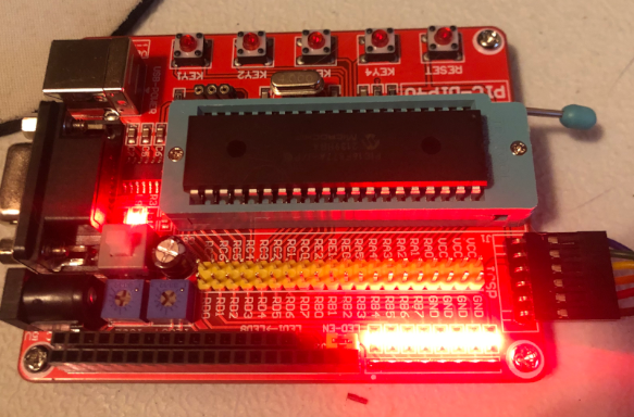
In this section, I’ll be using MPLAB X version 5.5. I settled on this version because it seemed stable. Also most of the documentation I’ve found by searching the internet. was pertinent in this version. I’ve also installed the XC8 Compiler, version 2.41. The Microcontroller I’m using is one of the most common: 16F877A. Additionally, I’m using a small training kit that I found on Amazon for around $15. This even came with the PIC processor.
Another item you’ll need is a PICKIT. This allows you to program the Microcontroller. For this setup, I’m using the PICKIT 4.
Struggles with Getting Started
The learning kit I’m using came with examples in C++. This worked just fine. However, I wanted to know how to program this controller in assembly. I’m used to programming vintage processors such as the Z80, 6502, and COSMAC. There are small details that tripped me up when programming the PIC. These include the use of PSECT instead of ORG. The labels for EQU statements do not have the “:” after them, whereas other labels do. Likewise, the PSECT originating points must be defined in the linker options. Additionally, there are configuration bits we need to set up in our code.
Another issue I had was with communication. My programming cable did not seem to fit well, so I was constantly fighting the connections. Another issue was that some of the procedures I searched for on the Internet did not apply to the version of MPLAB I was using. On the other hand, I made some silly mistakes that caused my program not to run. This was creating a frustrating experience when getting started. Once I had a light flashing though, my confidence was high, and I began to enjoy the PIC Microcontroller.
Creating a new project for Programming the PIC Microcontroller in Assembly
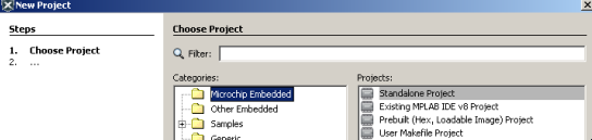
To begin, we’ll open MPLABX (v5.5). Be sure to give the IDE some time to open, and settle down. We’ll click File | New Project, and choose a “Standalone Project”. Click Next.
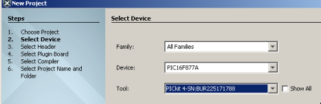
At this point, we need to select the microcontroller that you are using. In this case, I’m using the PIC16F877A. Be sure to choose the tool you are using. I’m using a PICKIT 4. After that, click “Next” Again.
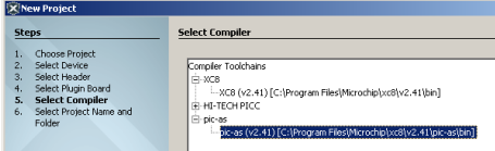
Next, choose your compiler. I’m going to use pic-as because this will be an assembly language program.
Now, we are ready to name the project. I’m going to call this “MyTestProject”.
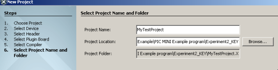
Click “Finish”.
Create a new Source File
At last, we are ready to create a new source file. In the project tree, right click “Source Files” and create a new source file. The type will be assembly. In the newer versions of MPLABX, this file will have the “.s” (source) extension.
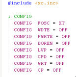
We’ll begin by adding some configuration bits. To begin, I’ll set all options to “OFF”, and select a crystal oscillator. I have an external 4MHz crystal.
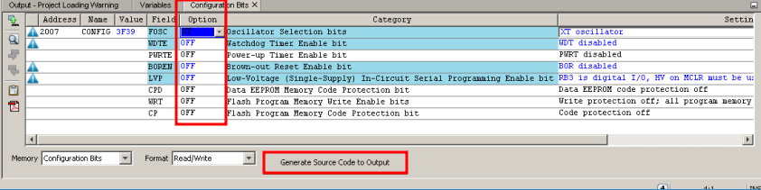
Select “Generate Source Code as Output”, and paste this code into your Source.s file.
At this point, we need to create a couple vectors. The reset vector will define our starting point in memory when the processor boots (or is reset). Additionally, we need to define an interrupt vector. Add the following code:
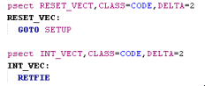
If you look at the reset vector, you will see, that we immediately jump to a label called setup. You can change this to MAIN, START, etc…. Later on, we’ll define this label in logic. We also have an interrupt vector. Since we’re just starting out, we won’t use interrupt vectors yet. We’ll just use RETFIE (return from interrupt vector).
Next, we need to define the memory location of these vectors. In order to do this, we go to the project properties. Simply right-click your project in the project tree, and go to properties. Go to the pic-as Linker, and choose “Custom Linker Options”.
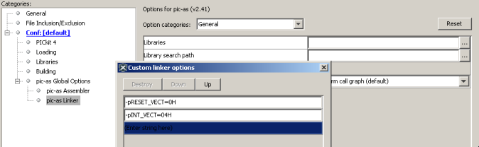
We need to add two entries…. -pRESET_VECT=0H…. also add -pINT_VECT=04H Be sure to spell these vectors in the exact same way you wrote them in your source code. Hit OK… then Apply, and OK.
Finishing the Program
Setup
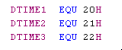
At this point, we are ready to finish writing our program. We’ll simply make a light flash. First, we’ll declare some delay variables. I’ll do this right after the config options.
Keep in mind that RESET_VECT will jump to a label called “SETUP”. We need to be sure to have this label in our source code. This is the section of the program where we’ll set up the states of the pins on the processor.
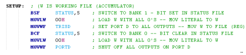
BSF STATUS,5 (Bit Set in File) will switch to bank 1 in memory. This is where we configure the pins (TRIS). TRIS is short for TRI-State. In this case, we load a 0 into the working register “W”. After that, we move the Working register to a FILE (which is a group of bits in memory). this will be TRISD. Moving a 0 to TRISD sets all of the pins on PORTD to output. (FFH would set them all to input). If you aren’t familiar with hexadecimal, read up on how numbering systems work.
The code you pasted for the configuration includes a file called “XC.INC”. This file contains labels that declare what memory location STATUS, TRISD, and PORTD point to. This makes life a bit easier for us, because we only have to remember the name of the memory location instead of the memory location itself. For example, BSF STATUS,5 is the same as BSF 03H,5.
Next, we use BCF STATUS,5 (Bit Clear in File) to clear bit 5. This will switch us back to bank 0. This is where PORTD is. We write to PORTD to actually control the outputs. Here, we’ll simply sink all of the outputs with 0.
Main Logic
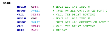
At this point, you are ready for the main logic. Basically, we are going to flash all of the lights at once. First, we move FFh onto PORTD. This sets all bits high. After that, we call a delay routine, which will get into a bit later. Call simply goes to a subroutine, then the subroutine has a RETurn instruction to come back to execute the next instruction after the call. Next we’ll write all 0’s to PORTD. Next, we delay again, and start all over.
Delay Logic
This logic is a bit harder to follow, but if you look at it closely, you’ll figure out how it works with a little time.
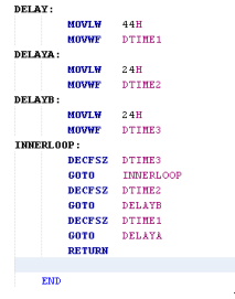
Basically, we are nesting delay loops to create a long delay. This simply keeps the processor busy, so we can actually see the light flash. Otherwise, it would flash so fast that it would appear to be always on.
Closely look at the delay loop to see if you can folow what is happening. You are already familiar with some of the instructions:
- MOVLW moves a literal value to the working register (W)
- MOVWF moves the working register to another file.
- DECFSZ Decrements the operand, and skips the next instruction if it’s zero.
- GOTO just jumps to a label
- RET simply returns to the next instruction after a call
Don’t forget to add the end statement after your logic.
Run the Program (Programming the PIC Microcontroller in Assembly)
At this point, you are ready to run your project. There is one other thing to check first, though. If you rely on your PICKIT to provide power to the controller, we must tell it to do so. Go to the properties of your project, and click on your PICKIT programming/debugging device. Under POWER, check the box to provide power to the microproessor.
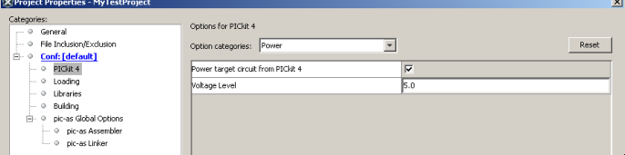
Hit OK. Now, right-click your project, and choose “RUN”.
For more information, visit the Main Site!
— Ricky Bryce