
Introduction to PLC-5 Counters
PLC-5 Counters count rung transitions. More specifically, the counters count the false to true transition. In the PLC-5, there are two types of counters: The Up Counter (CTU), and the Down Counter (CTD). While you won’t always see a CTD, it’s almost always associated with a CTU.
For example, you might use an Up Counter to count parts on a conveyor. At the same time, you might use a CTD for rejected parts. Since the CTU and CTD use the same data table address, your Accumulated value would represent the total number of good parts. Another common use is simply for troubleshooting. Basically, you can just count the number of times a bit goes true, such as an alarm, or limit switch. For example, if you wiggle a wire, and you see 10 counts in 2 seconds, that might indicate a bad connection.
Additionally, you might use the two counters to count the total number of items between to areas of a conveyor. When a part enters a conveyor zone, the counter counts up. When a part comes out of a zone, the counter’s accumulated value will decrease. Therefore, the accumulated value would represent the total number of items in any area of a conveyor.
Data Table
At this point, let’s look at the data tables in the PLC-5. As you can see, the default counter file is C5. You can expand this file to contain up to 1000 counters. Always be careful to watch your processor’s memory usage though. If you need more counters, you can always create a new counter file. File #999 is the highest Data File number in the PLC-5.
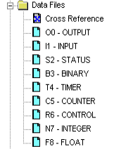
In this case, I’ve already expanded the data file by going to properties.
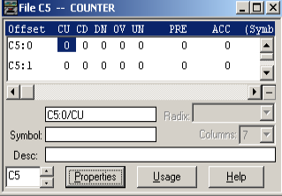
The CU bit is the “Count Up” bit. This goes true when the CTU instruction goes true. Likewise, CD is your count down bit. This goes true when the CTD instruction is true. The Done (DN Bit) goes true whenever the accumulated is equal to or above the preset. Additionally, you have the OV Bit. This Overflow bit goes true when the counter exceeds 32767. Conversely, you have the UN (Underflow) bit, which goes true when the counter counts all the way down past -32768. These values are the limitation for for a 16 bit signed integer. 0 is considered to be positive.
Obviously, PRE is your preset, and ACC is the accumulated value.
Counter Logic
Let’s take a look at some counter logic. In this example, we have a CTU, CTD, and RES.
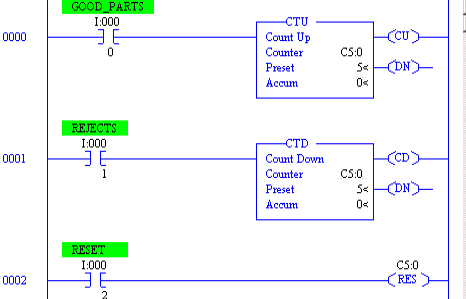
In this case, the logic is very simple. When a photo eye detects a good part, the count up counter will increment. Likewise, when a second photo eye detects rejects, the count down counter decrements the accumulated value. At any time, you clear the conveyor, you might hit a reset button. This resets the counter back to zero.
It’s important to realize that the CTU and CTD act as a pair. There is only one counter in use, and that is C5:0. Whenever the CTU goes true, you will see the value increment in both instructions. Conversely, when the CTD goes true, the value goes down on both instructions.
The PLC-5 Instruction Set Reference manual is a good document to keep on hand if you need help with any instruction.
For other information on the PLC-5, visit the PLC-5 Category Page!
— Ricky Bryce
These are really excellent articles on explaining the basic concepts on PLC programming. They really help me out with learning PLC. Thank you very much. God bless.
Thank you. It’s great to hear from you, and I’m glad the posts are helping! Take care — Ricky