
Introduction to PLC Status Indicators
PLC Status indicators will tell us a lot about our system. Above all, they help us to troubleshoot the system to minimize down time. For example, if an output status light is on, that tells us the logic is calling for the output. In this case, you know the problem is between the output module, and the field device. That is, as long as the output module itself has power, and it’s switching device is OK.
In this post, we’ll go through the different status indicators that you will encounter. If a status light is not described here, you can always consult the user manual for the module.
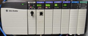
Processor Status Lights
The processor status indicators will describe the state of your processor. This is where the program resides. Normally, the processor is in the left most slot, although it might reside in any slot. This is the module with the key switch.
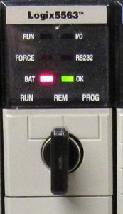
Left edge of Processor
BAT — This is the Battery indicator. In the event that your battery is low, the battery light will energize solid red. Please change the battery within one to two days.
Force — Forces simulate real world jumpers. Because forcing overrides the normal operation of your equipment, you should always pay attention to the force light. If this light is solid amber, forces have been enabled. If any forces are in the processor, they are active. In RSLogix / Studio 5000, use the Search feature to find them. On the other hand, if the force light is blinking amber, forces are installed, but not enabled.
Run — Whenever the run light solid green, the system is running. The processor is scanning the logic. Obviously, if the run light is not on, the system is not running.
Right Edge of Processor
I/O — This indicator should be solid green. From time to time, you might loose power to a remote chassis. In addition, a module might fail. When the I/O light flashes green, there is a problem with some I/O in your system. If you have a new processor, with an alphanumeric display, you will know where the problem is. Otherwise, go online with your processor, and scroll to the bottom of the I/O tree. Look for yellow caution signs on the I/O modules. Go to the properties of any module which indicates a problem. Next, click on the “Communication” tab. At this point, you will see a description of the error.
It’s important to realize that if you have a problem with communication to a remote chassis, every module in that chassis will have a caution on it. In this case, just go to the properties of the first module that indicates a problem.
RS232 — This indicator simply flickers as data transfers across the RS232 cable.
OK — This light should be solid green. In the event that the processor has a hardware problem, this light will be solid red. Basically, if there is a problem in the program, this indicator will flash red. A flashing red indicator is a recoverable fault. Obviously, if the OK light is not solid green, your system will be down.
Other PLC Status Indicators
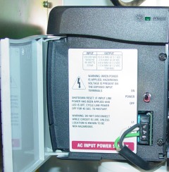
Power Supply — If the power supply indicator is on, then the power supply is supplying power to the chassis. Otherwise, if you have voltage to the power supply, and the indicator is not on, the power supply has shut down. This could be due to excessive load, a shorted module or backplane, or a bad power supply. Try to cycle power off for one minute, then back on.
I/O Modules
OK — This indicator should be solid green. Basically, this means the processor is actively controlling the I/O. Flashing green indicates the processor is not actively controlling the I/O. Make sure the processor is in run mode. Solid red indicates a hardware problem. On the other hand, flashing red indicates that the module lost it’s communication.
Fuse — Explicitly for output modules, the fuse indicator shows a blown fuse. For electronically fused modules, you would reset the fuse in software, or power cycle the module.
I/O Status — For input modules, we have power to the input terminal with reference to common. On the other hand, if you have an output module, this indicates the processor is calling for the output to energize.
Ethernet PLC Status Indicators
Link — This will normally be flashing green. This indicates the module is sending and receiving traffic. Solid green indicates the module is active, however, there is no network traffic to the module.
OK — We want this indicator to be solid green. Flashing green indicates the module is not configured. Flashing red is a recoverable fault. Furthermore, solid red is a hardware fault.
NET — ,Although this will normally be solid green, however, flashing green indicates that the module is OK, but no connections are configured. On the other hand, solid red indicates a conflict. This could be due to a duplicate IP address on the network.
For more information on ControlLogix, visit the ControlLogix Category Page!
— Ricky Bryce