
Introduction to ControlLogix Rate Limiter (RLIM)
We use the ControlLogix Rate Limiter (RLIM) to slow the rate of change from a tag. For example, if the operator changes a setpoint, we might not want to feed the new setpoint directly to a PID. This could cause a large bump in the process. We can run the value the an RLIM instruction. This would ramp the setpoint change. After that, we might feed the output of the RLIM instruction into the setpoint.
The Rate Limiter instruction is useful in other processes as well. For example, the speed of a motor. A fast change in motor speed could cause the motor to jump. To slow the rate of change, we would also run this value through the RLIM instruction. Another example is a direct valve position command.
By using the RLIM instruction, we specify the ramp speed in both directions. In other words, we can ramp up at a different speed than when ramping down.
It’s important to realize the RLIM is not available in Ladder. We can use this with function blocks, or structured text.
Create Your Tags
Before we begin, we’ll create a couple tags. This will demonstrate how the Rate Limiter works. I’m going to add these into program tags. We’ll create two tags. The first is RLIMInput. Likewise, the second tag is RLIMOutput. Both tags will have the REAL Data type. The instruction will also work with other data types such as DINT. REAL allows us to have a decimal point. This provides more precision.

Create your Logic
In this case, I’ve created a new Function Block Routine. Keep in mind that if we add a subroutine, we must have a JSR instruction for the routine to execute.
Let’s add the following logic into the function block routine:
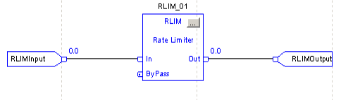
Configure the Instruction
At this point, we’ll go into the configuration of the instruction. To do this, we’ll click the ellipsis. This is in the grey square at the top right corner of the instruction.
For this example, we’ll set both the accel and decel rates to 30. This will give us some time to see what the instruction is doing.
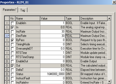
This instruction is in a periodic task. I will use 0 for the timing mode. This is default. Other options are overs ample, and real time sampling..
As you can see, we can also enable the bypass bit. Doing so will feed the input directly to the output. You can use this bit when you need to make quick adjustments to the output.
The instruction also provides status information about our setup. For example, if we enter a negative value for ramp up time, the instruction will fault. The DeltaT output is simply the amount of time between updates.
After you make a change, be sure to press ENTER, then we’ll hit “Apply”, then “OK”
Test Your Work
Be sure you have finalized. If you are offline, then you can download. Realize, though, that if you download, your equipment will likely shut down. The processor must go to program mode to accept the download.
Let’s change the input to 500, and we’ll watch the output ramp up.

As you can see, after we change the input to 500, the output begins to change. After 30 seconds, the output will reach 500.
Likewise, we’ll test our instruction while ramping down. Change the input back to 0. Eventually, after 30 seconds, your output will go to zero.
Summary
In short, the RLIM instruction limits the rate of change of a variable. We can limit the rate of change in both directions. When the input changes, the output will ramp up or down linearly. If you need an immediate change of the output, set the bypass bit.
For more information, visit the ControlLogix Category Page!
— Ricky Bryce