
How I’m Lowering the RC2014 Baud Rate
My approach to Lowering the RC2014 Baud Rate is very simple. I simply looked at the original clock circuit, and built another frequency divider. In this post, we’ll discuss how easy that is to do. You already have the ability to set your jumpers to adjust the baud rate down to 4800. With this setup, however, we can run Serial B at 2400, 1200, 600, or even as low as 300 baud. In this case, my approach was to use an external 74HCT393. This is a binary ripple counter. Obviously, we need to supply power. Then we just pick a frequency off the clock 2 header, and divide that by 16.
The reason we might need to do this is to communicate with devices that do not support higher baud rates. For example, I have a PAL-1 that runs at 1200 bps.
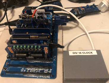
In my setup, I’m running a Zed Pro with an enhanced bus backplane. I have a dual clock module, and a dual serial module. I’m leaving clock 1 at 7.3728 MHz, and the purpose of this post is to change the baud rate for Serial B by reducing the baud rate of Clock 2.
Building the Module
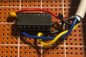
First, you need to obtain an additional 74HCT393 IC. You can see the pinouts for this module here. I simply supplied 5V and GND to pins 14 and 7 respectively. Additionally, I placed a 100pF capacitor between these two pins on the IC. This is a bypass capacitor to eliminate the ripple effect in the supply to our chip. Keep in mind that even if you have a supply with good regulation, you still should use a bypass capacitor. The voltage drop in your supply lines cause a ripple effect in the power to our chip.
We need two other connections. The blue wire in this case is our source frequency. I am connecting this to pin #1 on the 74HCT393. The yellow wire is our frequency that we are dividing by 16. I’m connecting this to pin #6. The only other connection we need to make is to tie the reset low. Simply connect pin #2 to ground.
Connecting to the Dual Clock Module
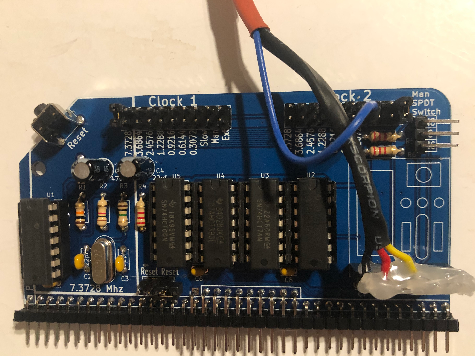
We can get the supply from the external clock header on the dual clock module. The left-most pin on the header is GND, and this is Pin #1. Pin #2 contains our 5V for VCC.
We also need to connect our yellow wire to pin #5. This is the external frequency supply.
Lastly, we need to move the jumper on the Clock 2 header to “External”. This is the far right pin.
At this point, you are ready to pick a supply frequency with the blue wire. The supply frequencies are on the bottom row of the dual row header.
If you select .0372, then your baud should be 300 for Serial B. Likewise, if you select .6144, then your baud rate will be 600 on serial port B. Once again, if you select .1288, then you should get 1200 baud. If you need to run 2400 baud, place the blue wire on the 2.4576 setting.
Summary of Lowering the RC2014 Baud Rate
In short, I simply used an additional 74HC393, and supplied power to the IC. Place a bypass capacitor across your power leads, and ground the clear signal. On the dual clock module, make your connections for power, and the external clock supply. Move the jumper to the “External” position for Clock 2. Pick a source frequency with your blue wire on the lower row of the dual clock 2 pin header.
As you can see, I simply hot glued the pin header to avoid any short circuits.
For more information, visit the RC2014 Category page!
— Ricky Bryce