
Introduction to the RTC Module for RC2014
The RTC Module for RC2014 allows your system to keep time. This module allows you to take advantage of the timestamp feature in Z80DOS, and ZPM. You can purchase this module on Tindie’s website.
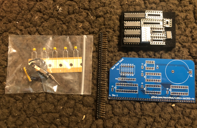
The module I am using arrived as a kit, and only took about 20 minutes to assemble. There are no surface mount components. All of the IC’s have sockets for easy replacement.
You have a set of DIP switches to adjust the address. The default address is for the last two switches to be up. The other for switches are down. This will give you an address of $C0. Since most governments are afraid of lithium batteries, you’ll have to purchase your CR2032 Separately.
Assembling the Kit
Low Profile Pieces
As always, I like to start off with the lowest profile parts first, so I added the IC Sockets to the board. Typically, I’ll put all of the sockets in place, then tape them into place. After that, I’ll just solder one pin of each side of the sockets.
For me, the tape never holds them perfectly in place. Remove the tape, and re-heat each soldered connection while holding pressure on the IC socket. Once the sockets are all perfectly in place, then you can solder all pins.
Next, I soldered the capacitors and resistor bank in the same way. The capacitors are not polarized, but you do have to pay attention to the direction you install the resistor bank. You can identify pin 1 by the white square on the PCB. Also, the resistor bank itself will have a dot, or other clear mark for pin #1.
After that, I installed the DIP Switches, and then the battery holder.
Final Pieces
Be careful when you install the header. It needs to have good alignment, so it will be straight when you plug the module into the backplane. I will usually place the header as straight as possible, then solder the center pin. Hold the module at different angles until you are satisfied that it’s straight. After that, I’ll solder both ends. It’s important to realize the header tends to bow a little bit, so be sure to apply pressure, and reheat both ends to ensure the whole header is straight, and against the PCB. Then, you can solder all pins.
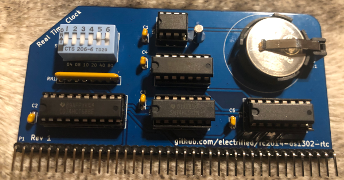
Lastly, I installed the crystal. Again, you don’t need to worry about polarity. I install this last because I don’t want it to move around and break the leads while I solder other parts of the board. Additionally, I placed a dab of hot glue on the crystal to prevent any movement.
Don’t forget to install your CR2032 battery.
Setting the system time for the RTC Module for RC2014
At this point, you can place the RTC Module into your RC2014 backplane. Be sure pin 1 on the RTC lines up with pin 1 on the backplae. You are ready to set the clock.
In this case, I’m using ROMWBW, which has a program called RTC.COM. This program allows you to set and view the time on the module.
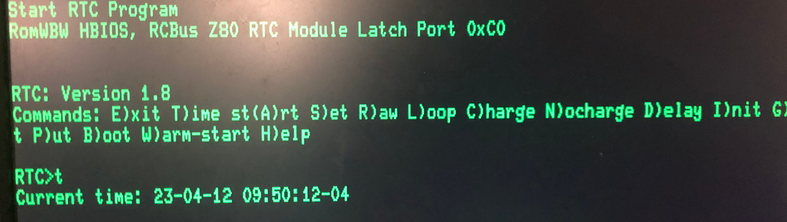
Press I to initialize the time. Each field will be 2 digits. You might have to try this a few times to get the hang of it. I’ll usually initialize the clock to 1 minute in the future. After that, I’ll look at the actual time. When the actual time catches up to the time I initialized the module with, I’ll press “S” to set the clock.
Next, you can press “T” to verify your time settings. Your RC2014 RTC is ready to go!
Summary of the RTC Module for RC2014
In short, there are no surface mount components, and just a few parts to solder on this module. Be sure you have a CR2032 battery on hand when your kit arrives. You can use RTC.COM to initialize and set the clock.
For more information, visit the Vintage Computers Category page!
— Ricky Bryce