
Introduction to PID Zero-Crossing Deadband
PID Zero-Crossing Deadband is a method to prevent too much action on the control variable. Particularly, if your process variable is noisy. Too much action on a field device will cause premature wear. This requires extra maintenance, and possibly more downtime.
The disadvantage to deadband can be detrimental. Once the process variable moves outside of the deadband, the controller must take more corrective action. This could lead to oscillations in your process. Too much deadband will likely cause the loop to become unstable. Effectively, you will turn your loop into an on/off switch.
Another key point is that some actuators and other controllers might have deadband already built into them.
A deadband without zero crossing will simply stop changing the control variable once the process variable is within the deadband. In this case, applying deadband may not help you at all.
With zero crossing deadband, the controller will continue to change the output until the process variable crosses the setpoint. Once the process variable crosses the setpoint, it will take no further action. That is to say the action stops until the process variable crosses the deadband again.
In this section, we’ll apply a deadband, and determine if it will be helpful. We’ll be using the ControlLogix processor for this example.
Background
Previously, we tuned a cascading loop, with flow and level. The level PIDE was the master. Our flow pide was the slave. We used our simulator to emulate a real world process.
Adding the Deadband
In the Level Control PIDE, we are going to add some deadband. After that, we’ll see the results. Normally, your deadband value will be very small. A typical deadband setting might be 0.25%. We are going to add 5% just to see the effects. This will help us to understand how the deadband works.
In the Level PIDE, let’s set the deadband at 5%. Keep in mind, this value is extremely high for most processes. We are merely doing this for now, so we can understand the operation of the deadband.
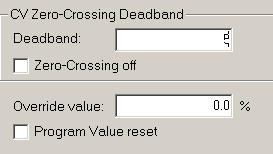
Remember the PIDE instruction defaults to zero crossing. For now, we do not want to shut zero crossing off.
Let’s observe the results.
Results of PID Zero-Crossing Deadband
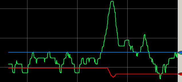
Notice that we have controller action until the process variable hits zero. Once this happened, the controller action stopped. The process variable is free to move around within 5% of the setpoint. The red line is our control variable. Blue is the setpoint, and red is the control variable.
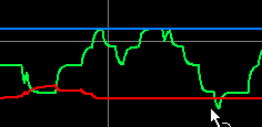
Now, notice that if we increase the load by 1%, the process variable falls below our threshold of 5%. This causes the controller action to restart. Controller action continues until the process variable crosses zero. At this point, the controller action stops. Control action does not restart until we exceed the deadband threshold.
Non Zero Crossing Deadband
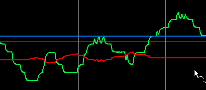
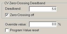
At this point, we’ll shut off Zero Crossing. This will likely result in a loop that is completely unstable if the deadband is too high. With non-zero crossing, any time the process variable is within 5% of the deadband, there is no control action.
First, let’s shut off zero crossing.
Now, let’s go back and look at our trend chart.
To observe the effects, decrease the load on your simulator by 1%.
Summary
To summarize, deadband could reduce controller action. Zero crossing deadband causes the control variable to act when the process variable exceeds the deadband. Controller action continues until the process variable crosses zero.
With non-zero crossing, the process variable is free to move around within the deadband. As soon as the process variable is back in range, the control action stops.
Keep in mind that if we add too much deadband, our process will become unstable.
— Ricky Bryce