
Introduction to Function Blocks for PlantPAx PID
In this section, we’ll add our Function Blocks for PlantPAx PID. In our previous sections, we imported the add-on instructions. At this point, we are ready to set up our function block logic.
If you have not already done so, created a periodic task with a program for the PID Logic. After that, add three routines:
- MainRoutine
- FlowControl
- LevelControl
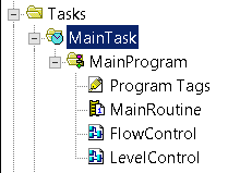
Be sure to go to the properties of your MainProgram, and make sure the MainRoutine is indeed configured as Main. Also, don’t forget to add your JSR Instructions to the MainRoutine. Otherwise, the processor will not scan FlowControl, or LevelControl.
Add your Logic to Function Blocks for PlantPAx PID
Analog Input for Flow
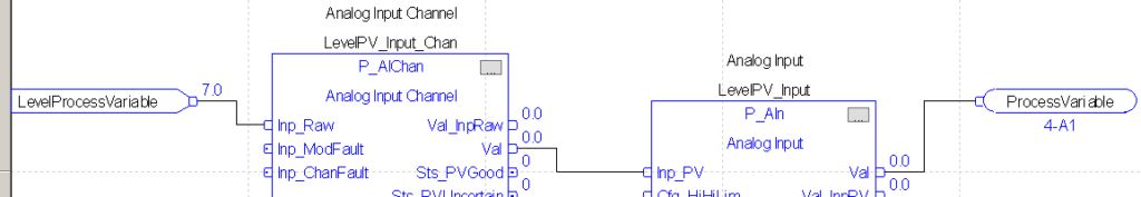
To begin, let’s open the FlowControl routine. On Sheet #1, we’ll add a PAIChan instruction and a P_AIn instruction. We’ll also need an IREF and an OCON. The OCON simply has a label, not a tag. This allows us to feed data into another sheet later on.
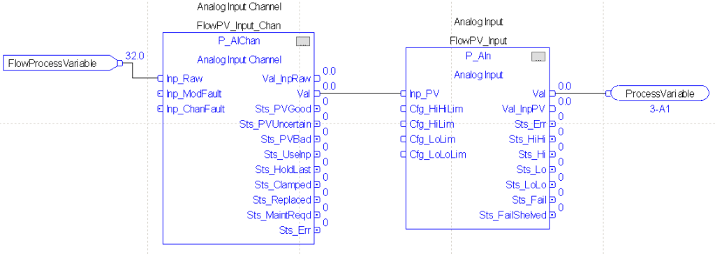
FlowProcessVariable is an alias that points to the Analog Input Channel that our Flow Process Variable connects to. Our P_AIChan instruction simply conditions the input, and checks for faults. The P_AIChan will provide a standard scaled value to the P_AIn instruction. We will configure these later on from the HMI Faceplate.
When you drop in the instructions, Studio 5000 creates a default tag name. Simply go to the properties of the default tag name, and rename them. The name of the channel is very important. The channel must have the exact same name of the P_AIn instruction it connects to… with one difference. The Channel needs “_Chan” immediately following the name of the analog input instruction. For the OREF, simply type the label “ProcessVariable”. On another sheet, we’ll feed this value to the PID instruction. The labels for IREF and OREF are local to the routine they reside in. This means that we can freely use these same labels on other routines. Remember, they are not tags.
Be sure to label the entire sheet as “FlowPV”. Enter the name in the upper right hand corner of sheet 1.
Flow Control
Analog Output for Flow
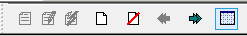
At this point, we’ll create a new sheet. Press the “New Sheet” icon. This is the third icon from the left of our function block toolbar.
Name this sheet “FlowCV”. This instruction will handle our analog output for the Control Variable. Set up your logic as follows:
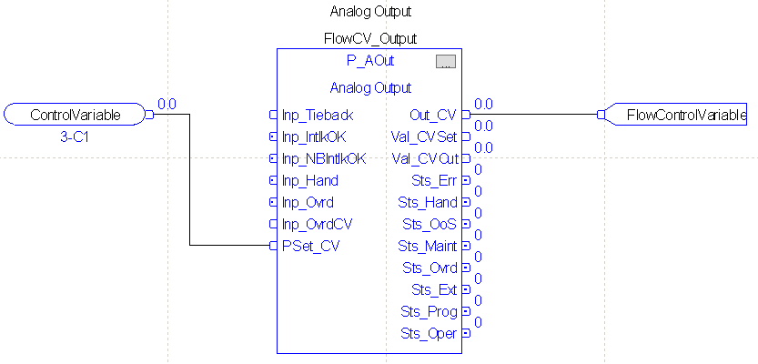
As you can see, we need an ICON (Input Connector), a P_AOut instruction, and an OREF. The ICON simply feeds the control variable in from the PID Instruction. You will need to go to the properties of the P_AOut instruction to turn on visibility for the PSet_CV. Do this before you attempt to tie the ICON into the P_AOut.
Lastly, our Out_CV of the P_AOut will go to the OREF. The tag on the OREF is our FlowControlVariable. This is simply an alias to the real world output channel that our field device connects to. Don’t forget to rename the tag for the P_AOut instruction. You must right click the tag name and edit the tag’s properties to do this.
P_PIDE Instruction for Flow
Lastly, we’ll add another sheet for the P_PIDE instruction in PlantPAx. Add another sheet as we did before. Be sure to label this sheet “FlowPID”. Set up your logic as follows:
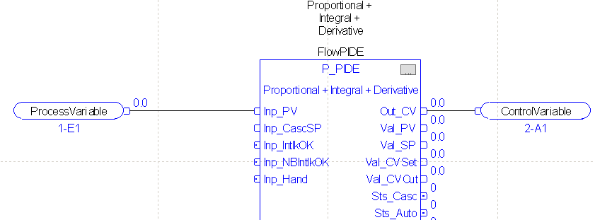
Please remember to rename the P_PIDE’s tag.
Level Control
Later on, we will set up a cascading PID system, and we’ll involve a tank level in that configuration. For now, let’s go ahead and set up the routine. Open your LevelControl Routine
Analog Input for Level
As before, on sheet 1, we’ll add the following logic:
Don’t forget to edit the properties of each instruction to rename the tag. This will help us to remember the purpose of the tag when we configure the HMI.
PID Instruction for Level Control
This time, since we will be using cascading control, we do not need a control variable. When we configure the cascading PID, the CV will go directly to the setpoint of our flow controller.
The only thing left is to set up the PID Instruction: Be sure to create the tag “SPFromLevelPID”. It will have a REAL data type.
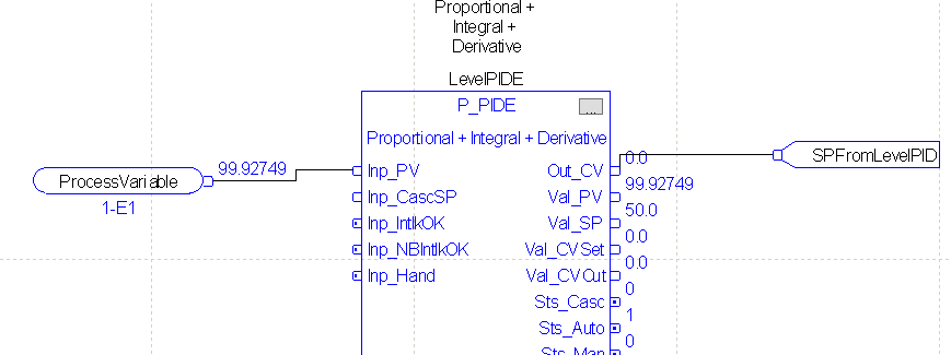
As before, don’t forget to rename the tag.
Summary
In Short, all we did in this section was add our logic. This logic will get the processvariable from the analog input channel. The logic then scales the value, and sends it to the PID. In the flow controller, we feed the output of the PID through an AOut instruction. This will scale engineering units back into raw data. The Analog Output channel uses this data to provide a voltage to our simulator. In the next section, we’ll associate the PlantPAx HMI objects to the tags we just created in our processor.
— Ricky Bryce