
Introduction to Inverting Q on the ELF MC
Certain firmware requires Inverting Q on the ELF MC (1802 ELF Membership Card). This is usually true when you have the front panel attached, which is revision J or later. In my case, I wanted to run Diskless ELF/OS (and still have the Front Panel) I burned the firmware at memory location 0000. After that, I set up the jumpers on the board so that U2 is LOW, and U8 is HIGH. At this point, I connected my terminal at 4800bps. When I hit enter, all I had on the terminal was garbage.
After reading up on this firmware at Lee Hart’s page, I realized that Q is inverted on my board compared to previous versions. This is the transmit signal from the ELF MC’s front panel.
To invert this signal, I used a 74HC00N IC, which is a NAND gate. We just have to set up the circuitry to operate as a NOT gate. This will invert the signal. In other words, when the ELF sends out a HIGH signal, the NOT gate converts this to a LOW signal. On the other hand, if the ELF sends a LOW signal, the NOT converts this to a HIGH signal.
Setting up the IC
My TTL programming cable has separate wires. I was able to keep the programmer’s transmit signal connected to the Front Panel. If you have a standard programmer, simply breakout the pins on a breadboard. This allows you to access each one individually with your breadboard jumpers.
The COSMAC Elf Front Panel’s transmit pin will need to go through our NOT gate, though. As I said before, I simply used a 74HC00N IC, and set up the circuitry to act as a NOT gate. NAND gates are very handy to have on hand, because it’s a universal gate. That is to say, we can make any type of gate by combining NAND gates together in various configurations. To create a NOT, just tie all the inputs together for the NAND gate. In this case, there are only two inputs for each gate.
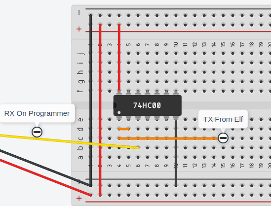
As you can see, the Transmit signal from the ELF connects to pins 1 and 2 of the NAND gate. Pin 3 of the NAND gate will connect to RX on your programmer.
In short, your connections will be as follows:
Programmer 1802 Elf MC Font Panel
GND ————————————–> GND
VCC ————————————–> VCC
TX —————————————-> RX
RX —————-| NOT | ————–> TX
Don’t forget that you need to ground pin 6 to bring the front panel out of standby mode.
Remember that you also need to supply VCC and GND to the NAND gate. Pin 7 of the 74HC00N is GND, and Pin 14 is VCC.
Connect to your Terminal after Inverting Q on the ELF MC
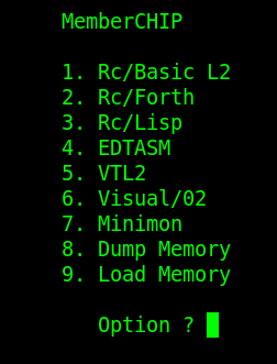
At this point, I used minicom to connect to the Membership Card at 4800/8/N/1. As soon as I pressed enter, I could see that I was up and running! This ROM supports several different programming languages that I wanted to experiment with.
Summary for Inverting Q on the ELF MC
In Summary, you are passing all of the signals through from your programmer to the Elf’s front panel, except for the programmer’s RX Pin. We need to add a NOT gate between the ELF’s TX Pin, and the Programmer’s RX Pin. Since the 1802 uses the Q output of the processor as Transmit, we are effectively inverting Q.
For my setup, I found a small wooden treasure box at Wal-Mart. The Elf MC fits nicely into this box with a small breadboard. I can even shut the lid with all of the connections in place. It’s important to realize, though, that when you use a breadboard, you are adding resistance on each connection.
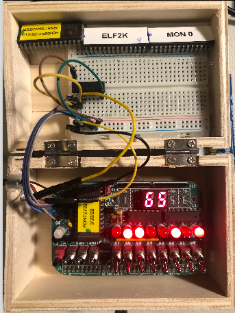
I like to use hot glue to hold these components in. This is because the hot glue is not permanent, and it’s easy to work with. You can easily break the bond of hot glue by using alcohol.
For more information, visit the Vintage Computer Cagegory Page!
— Ricky Bryce