
Introduction to ControlLogix Up/Dn Accumulator (UPDN)
The ControlLogix Up/Dn Accumulator (UPDN) instruction might seem a little confusing at first. It’s operation is very simple though. For example, we have two flow rates of a tank. The first rate is flow in. Likewise, the second rate is flow out. We can pulse the UP/DN instruction to get an idea of the total product in the tank. In other words, we get a good idea of the tank level. This is a crude example, because flow rates are usually noisy. To understand the instruction itself, though, we’ll use this process for example.
Whenever the HOLD bit goes low, the UPDN takes subtracts INMINUS from INPLUS. It then adds the result to the accumulator. Therefore, if our flow rates are in gallons / second, we can sample every second. The accumulator will reflect total gallons in a tank. It’s important to realize that when the HOLD bit is low, the operation occurs every scan. Therefore, we’ll simply pulse the hold bit LOW every second.
The Initialize bit will reset the accumulator back to the initial value. In this case, that will be zero.
Add the Logic for the ControlLogix Up/Dn Accumulator (UPDN)
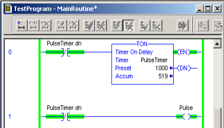
First, we’ll add a self running timer. This timer resets itself every 1000ms. This means the DN bit goes true every second. At the same time, we’ll use the NOT of the DN bit to trigger our PULSE tag. In other words, the pulse tag will go low every second for 1 scan. We’ll use this pulse to our HOLD input. This means the instruction will always be held, except for one scan per second.
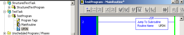
At this point, we’ll add the UPDN instruction to a function block. We have to create a function block routine. Don’t forget to add your JSR to the MainRoutine. This allows the subroutine to execute.
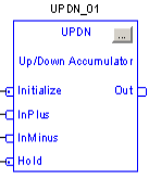
Next, we’ll add the UPDN instruction to the UPDN routine.
Click the Ellipsis on the instruction to configure parameters. This is in the grey box at the upper right corner of the instruction.
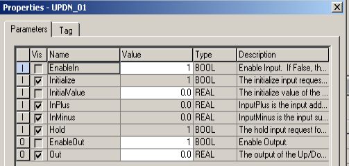
As you can see, we need to check the VIS field for INITIALIZE and HOLD. This adds a node on the instruction face. Obviously, this allows us to feed tags into those parameters.
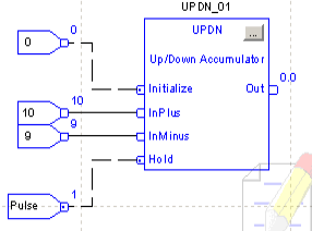
It’s important to realize that you will usually feed TAGS into the INPLUS and INMINUS. Too keep things simple, I’m simply using a constant. You can use REAL tags. That is to say, tags that can have a decimal point in the value.
Keep in mind that our Pulse bit goes LOW every second. When the Pulse bit goes low, the instruction stops holding for one scan. In other words, we will end up with one calculation per second.
Test Your Work
If this instruction is working well, we’ll be simulating 10 gallons per second entering a tank. Likewise, we are simulating a draw of 9 gallons per second. This means that every second we will add one gallon to the tank. In this case, we’ll assume the tank starts off as empty.
Finalize your work, and every second, you should see the accumulator increment by 1.
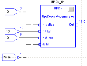
If you see the accumulator increment every second, then you have the UPDN set up as per this example.
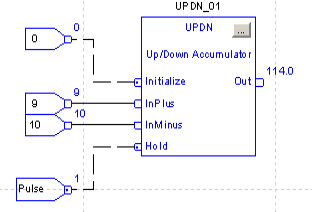
Obviously, if we reverse INPLUS and INMINUS, the accumulator should go down every second. This is because we are drawing more from the tank than we fill.
In my example, I was over 120 before finalizing. Obviously if our flow out of the tank is greater than the flow in, then the tank level will decrease. Here, I can see the tank is decreasing by one gallon every second.
Summary
In short, the UPDN instruction is for integrating processes. That is to say, we continue to add or subtract from the accumulator over time. It’s a simple way to manipulate data for integrating processes.
For more information, visit the ControlLogix Category Page!
— Ricky Bryce