
Introduction to the COSMAC 1802 LCD Timer
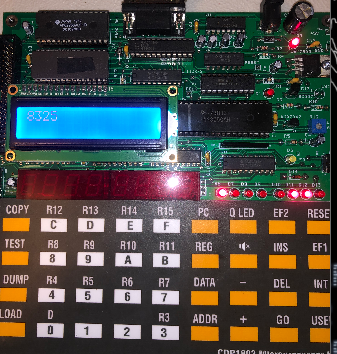
In this section, we’ll build a COSMAC 1802 LCD Timer. I’m using the CDP1802 Microprocessor kit for this with an LCD display. The code will also display the value of the timer (up to 255) on the LED indicators. Basically, to run the watch, just go to memory location 8000, and press GO. In the future I’ll add new features to this stop watch using the EF1 and EF2 inputs for start and stop control. For now, we’ll just keep things simple. I’m just learning the COSMAC myself, so I’m sure there are better ways of doing this, but projects like this help us all to learn. Every programmer has different methods.
I’m using the A18 Assembler to give us an Intel Hex file. After that, we can load that hex file onto the COSMAC. I’m using the LST file below as an example, and you can use the object code if you prefer keypad entry.
For the LCD control, I used the CDP1802 Microprocessor Kit workbook as an example.
Create Aliases
Before we begin, there are a few things we need to do. We’ll create some aliases that will help us with the logic later on. Additionally, we need to set the files origin at 8000H. As I said before, you may need to manipulate the code for it to work on your own COSMAC unit.
   7200                 LCD_CWR:	EQU	7200H
   7201                 LCD_DWR:	EQU	7201H
   7202                 LCD_CRD:	EQU	7202h
   7203                 LCD_DRD:	EQU	7203H

   8000                 	org	8000H
   0000                 R0	EQU	0
   0001                 R1	EQU	1
   0002                 R2	EQU	2
   0003                 R3	EQU	3
   0004                 R4	EQU	4
   0005                 R5	EQU	5
   0006                 R6	EQU	6
   0007                 R7	EQU	7
   0008                 R8	EQU	8
   0009                 R9	EQU	9
   000a                 RA	EQU	10
   000b                 RB	EQU	11
   000c                 RC	EQU	12
   000d                 RD	EQU	13
   000e                 RE	EQU	14
   000f                 RF	EQU	15
Initialize the Registers for the COSMAC 1802 LCD Timer
At this point, we need to put some initial values into the registers. That way, our display is sure to start at zero. At the end of this section, we’ll simply jump to the main loop.
   8000   f8 00         		LDI	00H
   8002   5b                            STR	RB
   8003   f8 70         		LDI	70H
   8005   ba            		PHI	RA
   8006   f8 00         		LDI	00H
   8008   aa            		PLO	RA
   8009   bb            		PHI     RB
   800a   ab            		PLO     RB
   800b   b7            		PHI	R7
   800c   a7            		PLO	R7
   800d   b8            		PHI	R8
   800e   a8            		PLO	R8
   800f   b9            		PHI	R9
   8010   a9            		PLO	R9
   8011   5a                            STR     RA
   8012   30 1c                         BR	MAIN
Create the LCD Subroutine
Next, we need a way to handle the LCD, and wait until it’s ready. Keep in mind that we are initially skipping over this subroutine. Later on, though, our logic will set the program counter to R3 to execute this routine. This subroutine is from the CDP1802 workbook. Basically, we enter the subroutine at memory cell 8015 We load R5, and AND this value with 80H. In other words, we check bit 3 to be high. If it’s not high, then the result is zero. Therefore, we continue to loop through this subroutine until the LCD is ready. Once it’s ready, then we branch up to 8014 where we set the program counter back to zero. This causes our logic to resume. This is a typical method in the COSMAC for calling subroutines.
  ;LCD DRIVERS
   8014   d0            RET_LCD1:	SEP	R0
   8015   05            LCD_READY:	LDN	R5
   8016   fa 80         		ANI	80H
   8018   3a 15         		BNZ     LCD_READY
   801a   30 14         		BR	RET_LCD1
Initialize the LCD Registers
Keep in mind that the COSMAC uses a lot of indirect addressing. We need to set some registers to point to the command and data registers for the LCD. Later on, when we store values with the STR command, those values do not go to the registers themselves. They go to the memory location the register contains. After setting up the registers to point to the correct memory locations, we place the value of 1 into register 4 to enable the LCD and set it up to receive data.
   801c   f8 72 b4 f8   MAIN:	LOAD	R4, LCD_CWR
   8020   00 a4
   8022   f8 72 b5 f8   		LOAD	R5, LCD_CRD
   8026   02 a5
   8028   f8 72 b6 f8   		LOAD    R6, LCD_DWR
   802c   01 a6
   802e   f8 80 b3 f8   		LOAD	R3, LCD_READY
   8032   15 a3
   8034   d3            		SEP	R3
   8035   f8 01         		LDI	01H
   8037   54            		STR	R4
   8038   d3            		SEP	R3
Write to the LCD
Later in this post, we’ll have counters in register 8 and 9. To optimize usage of the registers, I used both the high and low bytes to store each digit we need to send to the LCD. The R9 High byte contains the data for the most significant digit (on the left). After that, R9 Low, contains the next digit, R8 High contains the third digit, and R8 Low contains the last digit. This gives us the ability to count to 9999 seconds.
Because the LCD displays data in ASCII, we need to add 30H to each digit to get into the numerical section of the ASCII code. After we write each digit to the R6 register, we need to set the program counter back to R3. This will execute the subroutine that waits for the LCD to become ready again. Remember, once the LCD is ready, our routine sets the program counter back to R0. This allows the COSMAC to resume execution where we left off. After we write all four digits to the display, we’ll branch down to the TIMER logic.
   8039   99            		GHI	R9
   803a   fc 30                         ADI     30H
   803c   56            		STR	R6
   803d   d3            		SEP	R3
   803e   89            		GLO	R9
   803f   fc 30         		ADI     30H
   8041   56            		STR	R6
   8042   d3            		SEP	R3
   8043   98            		GHI	R8
   8044   fc 30         		ADI     30H
   8046   56            		STR	R6
   8047   d3            		SEP	R3
   8048   88            		GLO	R8
   8049   fc 30         		ADI     30H
   804b   56            		STR	R6
   804c   d3            		SEP	R3
   804d   30 4f         		BR	TIMER
Set up your Delays for the COSMAC 1802 LCD Timer
In order to increment our seconds, we need to keep the processor busy until one second passes. Here, I am creating 4 delay loops. I’m nesting three of the loops. By adjusting any one of the values in INIT0, INIT1, or INIT2, you are performing a “Course Adjust” to the time delay. The value of INIT3 is for a FINE adjust. If you find that you need even more fine tuning, you can simply add some NOP’s to the fine adjust loop. For very fine tuning, you can add NOPS after the loop. I could have used the 10ms tick as a timer, but not everyone will have that available. That’s why I chose to use the delay loops.
                        ;R8 is two LSDS
                        ;R9 is two MSDS
                        ;RA is for the GPIO
                        ;RB is the counter
                        ;RC is loop 0
                        ;RD is loop 1
                        ;RE is loop 2
                        ;RF is loop 3 fine tune
   804f   d0            TIMER:		SEP	R0
   8050   f8 10         INIT0:		LDI	010H
   8052   ac            DLY0:		PLO	RC
   8053   f8 10         INIT1:		LDI	010H
   8055   ad            DLY1:		PLO	RD
   8056   f8 de         INIT2:		LDI	0DEH
   8058   ae            DLY2:		PLO	RE
   8059   2e            		DEC	RE
   805a   8e            		GLO	RE
   805b   3a 58         		BNZ	DLY2
   805d   2d            		DEC	RD
   805e   8d            		GLO	RD
   805f   3a 55         		BNZ	DLY1
   8061   2c            		DEC	RC
   8062   8c            		GLO	RC
   8063   3a 52         		BNZ	DLY0
   8065   f8 f0         INIT3:	        LDI	0F0H
   8067   af            DLY3:	        PLO	RF
   8068   2f            		DEC	RF
   8069   8f            		GLO	RF
   806a   c4            		NOP
   806b   3a 67         		BNZ	DLY3
Separate out the Digits
Remember, for the LCD display, we need all of the digits to be separate. Keep in mind that R9 High/Low contain the most significant digits. R8 High/Low contain the least significant digits. To begin, we get the value of RB add 1, and store this value back to RB. The problem, though, is that we don’t have a DECIMAL mode like we have on the 6502. For this reason, after the ONES place gets to 0AH, we need to branch to the TENS. This will reset the ONES portion of R8, and increment the TENS portion. We repeat this for all four digits.
After we reach 9999 seconds, we’ll just have it roll over. You can extend this to as many digits as you need. In this case, four was enough for me.
After that, we go back to MAIN.
   806d   8b            		GLO	RB
   806e   fc 01         		ADI	01H
   8070   ab            		PLO	RB
   8071   5a            		STR	RA
   8072   88            ONES:		GLO	R8
   8073   fc 01         		ADI	01H
   8075   a8            		PLO	R8
   8076   88            		GLO	R8
   8077   fb 0a         		XRI	0AH
   8079   3a 1c         		BNZ	MAIN
   807b   30 7d         		BR	TENS
   807d   f8 00         TENS:		LDI	00H
   807f   a8            		PLO	R8
   8080   98            		GHI     R8
   8081   fc 01         		ADI	01H
   8083   b8            		PHI	R8
   8084   98            		GHI	R8
   8085   fb 0a         		XRI	0AH
   8087   3a 1c         		BNZ	MAIN
   8089   30 8b         		BR	HUNDREDS
   808b   f8 00         HUNDREDS:	LDI	00H
   808d   b8            		PHI	R8
   808e   89            		GLO	R9
   808f   fc 01         		ADI	01H
   8091   a9            		PLO	R9
   8092   89            		GLO	R9
   8093   fb 0a         		XRI	0AH
   8095   3a 1c         		BNZ	MAIN
   8097   30 99         		BR	THOUSANDS
   8099   f8 00         THOUSANDS:	LDI	00H
   809b   a9            		PLO	R9
   809c   99            		GHI	R9
   809d   fc 01         		ADI	01H
   809f   b9            		PHI	R9
   80a0   99            		GHI	R9
   80a1   fb 0a         		XRI	0AH
   80a3   3a 1c         		BNZ	MAIN
   80a5   30 a7         		BR	ZERO
   80a7   f8 00         ZERO:		LDI	00H
   80a9   a9            		PLO	R9
   80aa   30 1c         		BR	MAIN
   80ac                 		END
Run Your Code
Once you have the logic into the unit, you can go back to the programs starting address. In this case, that is 8000H. Press GO, and your timer should run!
For more information, check out the COSMAC Category page!
— Ricky Bryce