
Introduction to Tuning an Arduino PID
In this section, we’ll discuss Tuning an Arduino PID loop. Before we begin, it’s important to familiarize ourselves with what PID is. PID stands for “Proportional, Integral, and Derivative”. Don’t let the name be intimidating though. It’s just a way to provide the exact amount of output we need to reach a given set point.
For example, we might want to heat a tank of water to 100 degrees Fahrenheit. We need to be able to achieve this under varying conditions such as the ambient (surrounding) temperature of the room. Additionally, we might be putting cold water into the tank from time to time, or taking hot water out. We need the controller to respond in a way to get the temperature back up to the set point, and hold it there as quickly as possible.
We do not want fluctuations. A simple temperature switch could do that. Keep in mind our goal is to provide just enough output to hold the temperature exactly where we want it.
For the rest of this post, we will use a heating process for example. This will be a forward acting process using the Independent (Traditional) PID formula). We will be using the heuristic method for tuning, which is usually the easiest for most of us using Arduino.
Although I try to make this information as accurate as possible, it’s your responsibility to verify any information before utilizing it. Especially in a process where equipment or personnel can be harmed. Please provide feedback in the comments section to clarify or correct anything in this post.
PID Terminology
At this point, let’s discuss the different terms you need to be familiar with when tuning a PID loop.
General Termiology
Process Varialble (Input) — This is the feedback we get from the system. This could be temperature or pressure, etc, depending on the process. The feedback can provide anywhere from 0 to 5 volts to an analog input pin. We just need to know the scaling. For example: 0v might represent a temperature of 50 degrees. Likewise, 5v might represent a temperature of 150 degrees. In this example, our input will be A0 (Analog Input 0). In the Arduino, a 0v signal will give us a 0 on the analog input channel. 5v will give us a value of 1023. In other words, with this setup, a value of 0 to 1023 represents the value of 50 to 150 degrees.
Control Variable (Output) — This is the output that the Arduino sends from a PWM pin. If you need a true analog output, you will need to set up a low pass filter with a capacitor and resistor. Basically, if you convert the pin to true analog output, then the Arduino will send a value of 0 to the output to get 0v through the low pass filter. A value of 255 would give you 5v out of the low pass filter.
SetPoint — This is the value we desire the process variable (input) to be.
Error — This is the difference between the SetPoint and the Process Variable (Input). In other words, this is the difference between where we are, and where we want to be.
P, I, and D Terminology
Proportional
We base the output from proportional solely on the amount of error (and our gain). The higher our gain is, the more output we will have for a given error. If we are at the set point, then there is no error. Therefore, there is no output. In a non-integrating process, this means that your process variable will drop. The process variable will continue to drop until there is enough error to provide enough output to make up for your losses.
Integral
We calculate integral based on time and error. Let’s say, we set the Ki tuning parameter to 0.1 repeats per second. For the time being, let’s also assume that we have 10% error. To understand this easier, let’s also say that the process variable is not changing. Our error remains at 10% for now regardless of the output.
Since we have 0.1 repeats per second, after 10 seconds, we will have 1 full repeat. Remember, our error remained at 10. In other words after 10 seconds, we will add 10% to the output. If we assume we started with Kp=1, then the output from proportional is 10% also. Basically, this means that after 10 seconds, our output would increase to 20%. After 20 Seconds, our output would be 30%, and so on. If our setting was .05 repeats per second, then we make the integral less aggressive. After 20 seconds, we would only have 1 full repeat, which means it takes 20 seconds to get to a total of 30% output (counting proportional).
Derivative
Finally, we have derivative. We base derivative on the rate of change of error. However, since most input values are a bit noisy, we don’t use derivative most of the time. This would cause excessive control action. The derivative setting is how far we look into the future to expect the error to be for a given slope. You can think of derivative as opposition to a change in the process variable. Keep in mind though, this opposition is in both directions. Derivative tries to prevent the process variable from falling so much, but also resists the process variable coming back up to the set point.
Begin Tuning an Arduino PID
At this point, let’s take a look at a simple sketch that I put into the Arduino. Attached to the Arduino, I have a PID simulator that I put together with another Arduino build.
/********************************************************
 * PID Basic Example
 * Reading analog input 0 to control analog PWM output 3
 ********************************************************/

#include <PID_v1.h>

#define PIN_INPUT 0
#define PIN_OUTPUT 3

long CurrentMillis = 0;
long LastMillis = 0;
//Define Variables we'll be connecting to
double Setpoint, Input, Output;

//Specify the links and initial tuning parameters
double Kp = 5, Ki = 0, Kd = 0;
PID myPID(&Input, &Output, &Setpoint, Kp, Ki, Kd, DIRECT);

void setup() {
  //initialize the variables we're linked to
  Input = analogRead(PIN_INPUT);
  Setpoint = 400;

  //turn the PID on
  myPID.SetMode(AUTOMATIC);
  Serial.begin(9600);
}

void loop() {
  CurrentMillis = millis();
  Input = analogRead(PIN_INPUT);
  myPID.Compute();
  analogWrite(PIN_OUTPUT, Output);

  // Serial Plotter Data
  if ((CurrentMillis - LastMillis) > 500){
      Serial.print("Input:");
      Serial.print(Input);
      Serial.print(",");
      Serial.print("Output:");
      Serial.println(Output);
      Serial.print(",");
      Serial.print("MinValue:");
      Serial.print(0);
      Serial.print(",");
      Serial.print("MaxValue:");
      Serial.print(600);
      Serial.print(",");
      LastMillis = CurrentMillis;
    }
}
As you can see, Kp is 5, and I’ve set the other values at 0 for Ki and Kd temporarily.
Tuning the Arduino PID for Proportional
First, we need to find out the minimum value of Kp causes instability. The loop is unstable when it continues to oscillate. Let’s look at this on the serial plotter.
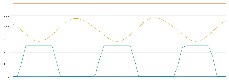
As you can see, the loop is unstable, and the output is saturating at 255, which is the max value. Let’s reduce Kp to 2.
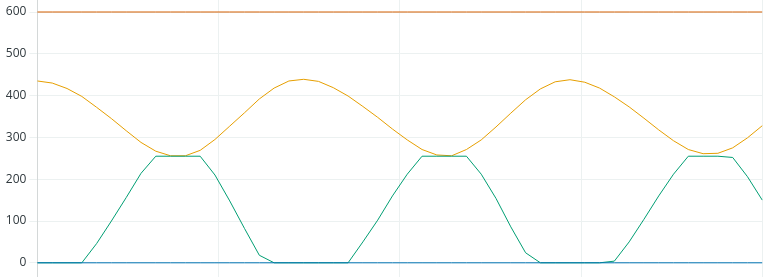
That helped, but we’re still unstable, and saturating again at times. Let’s try 1.
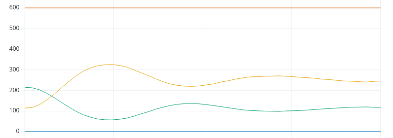
We’re fairly stable at 1, so let’s try 1.5:
As you can see, we went into constant oscillation. You can narrow this down further if you like, but we’ll run with this value. The definition of instability is when the process variable continues to oscillate with the same amplitude, or gets worse.
At this point, we need to write down the amount of time peak to peak, or trough to trough. It looks like this will be about 10 seconds.
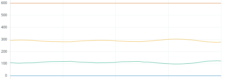
Additionally, since Kp is unstable at 1.5, we need to cut this in half. Our new Kp will be .75. Let’s see what our chart looks like with this new Kp.
Tuning an Arduino PID for Integral
Now that we found the value for Kp, the Integral is easy. For Ki, we’ll just take Kp divided by the natural period. This will be 0.75 / 10 seconds. Let’s try a Ki with 0.075, and let’s see if we get up to the setpoint.
Remember, our Set Point was 400.
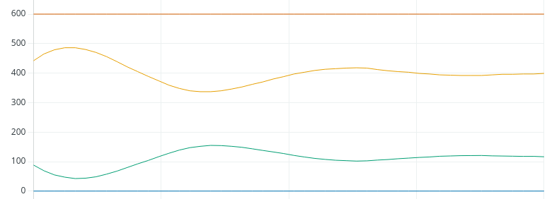
Looks like we landed it!
Tuning an Arduino PID for Derivative
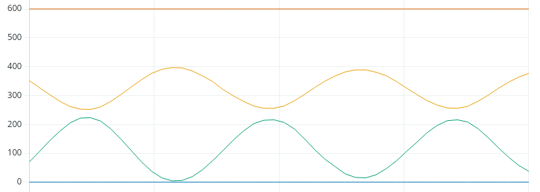
Now that we are confident, let’s see what will happen if we add derivative. To calculate derivative, we’ll take Kp * (1/8th of the natural period). In this case, that will be 0.75 * 1.25. Therefore, let’s try a Kd of 0.938.
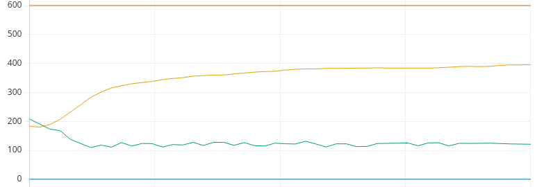
As you can see, we did achieve the set point, and it appears to be stable. However, we do see a lot more control action, although small. If this was a valve, you would be performing more maintenance on the valve due to the constant control action. One solution is to dampen the PV by using an average. However, by doing this, you also simulate more process lag, and cannot tune your loop quite as tight.
Summary
In short, increase Kp until your loop becomes unstable. At that point, record the natural period. Cut Kp in half, then use Kp / natural period for your Ki variable. If you use derivative, it will be Kp * (1/8th of the natural period). Please provide your feedback and corrections below. I’m sure there are some details of this post that need refined! There are other tuning methods out there using different procedures. You can just do a google search to find them, and choose whichever method works best for you!
For more information, visit the intermediate Arduino Page!
— Ricky Bryce