
Introduction to using RS232 on the RC2014
In this section, we’ll be using RS232 on the RC2014. In this case, I just purchased a generic module for this. There are several reasons we might want to use RS232. In my case, I wanted to communicate to a BASIC module on an automation controller. I also wanted the ability to communicate with other vintage computers that have RS232 ports. RS232 is still a common protocol. However, fewer devices are using it now 10 or 20 years ago.
Ideally, we would want our RS232 signal to be around 12 volts (plus and minus). Most devices however will operate in the 5 to 10 volt range. Some will work on as little as 3 volts. At any rate, to ensure compatibility with most devices, the generic module with a MAX232 chip uses charge pumps to generate + and – 10v.
This set up does not use flow control. Once you have communication working, you can utilize the unused channel of your MAX232 to expand and improve your own setup.
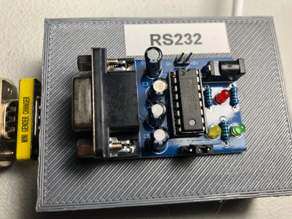
The RS232 Module
I had a lot of trouble with this module. It was continuously overheating, and latching up. This appears to be a frustrating problem that a lot of users have. I made some changes that worked for me. First, look at the wiring diagram for the specific IC that you are using. In my case, it was the MAX232 Wiring Diagram.
The first thing I noticed on this module is that the bypass capacitor was missing on the module. I placed a 1uF capacitor between VCC and GND.
Secondly, I replaced all of the 10uF capacitors with 1uF. Then lastly, I placed a 22 Ohm resistor in series with the power input (5v) to limit current to the module.
Thirdly, I grounded the unused TTL Input to prevent the IC from oscillating due to noise.
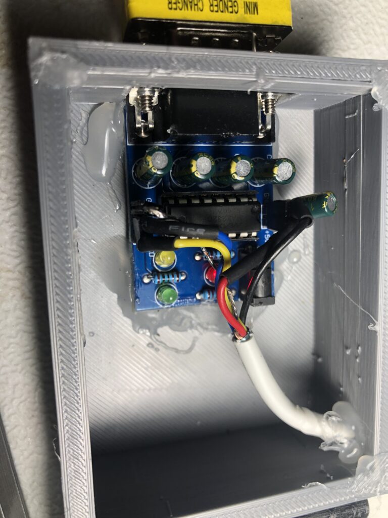
As you can see, I had to remove the module several times to try different ideas to prevent the overheating. I made a mess of the hot glue, but I’ll deal with that later. It’s inside of the case anyway.
Connect to your RC2014
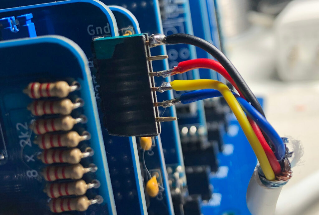
When we connect to the RC2014, be sure to install the power jumper for the serial port. In this case, I have a dual serial module, and am connecting to port B. Ground goes to the top terminal. Skip the next pin in the header, then connect VCC (5v). After that, connect to the RC2014’s Transmit pin (Yellow wire). Finally connect to the RC2014’s Receive pin (blue wire).
It’s important to realize that the Transmit pin of the RC2014 connects to the Receive pin of the MAX232 module, and vice versa. I’ve noticed that some RS232 modules have labels that are backwards from others. You can check your data direction by looking at the schematic, and using your meter. Or, you can just try it. If it doesn’t work, try swapping transmit and receive.
After I connect the wires, I always put some non-conductive hot glue over the connections to keep them from shorting. Then you can print a nice cover for the cables, and enclosure if you like.
Connect to your PC Using RS232 on the RC2014
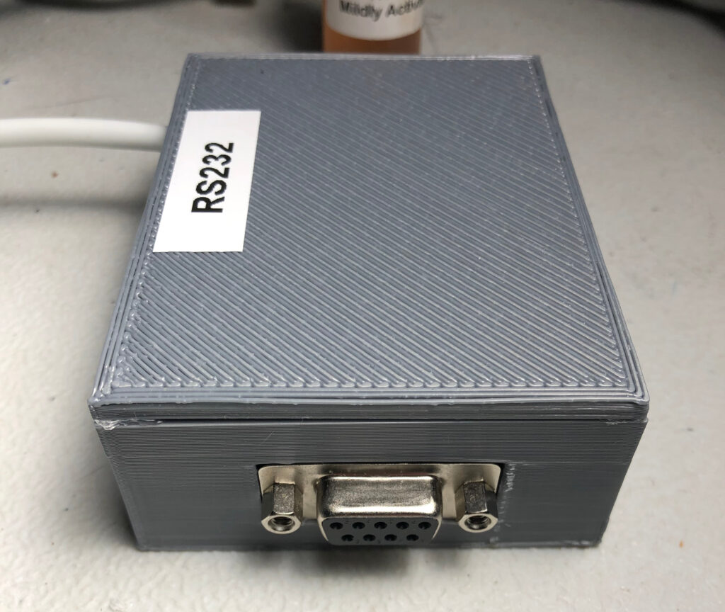
If you wish to connect to your PC to test the module, you will probably need a USB to RS232 converter. I’m just using the cheapest adapter I could find, and it’s working just fine. Also, you will need a serial extension cable (Not NULL Modem). If you have a standard serial cable that is female on both ends, you will need a gender changer to connect to the specific module that I used.
After you connect the USB to serial adapter to your PC, go to Device Manager if you are using Windows. Under PORTS, you can see what COM port number you need to use in your terminal. Look at CLOCK 2’s jumper to determine what baud rate you need to run if you are connecting to Serial Port B. Obviously, if you are using this on Serial Port A, then you will need to check the jumper settings for CLOCK 1 on the dual clock module.
Powering up the Module
When you apply power to the module, check to be sure the IC is not overheating. Cheap modules, and knockoff IC’s will often have this problem. I emphasize: Compare your module against the official wiring diagram. Check the internal pull up / pull down resistors. Be careful to find the correct wiring diagram for your exact module. For example, the TI chip varies slightly from the Maxim chip. If you still have a problem, place a 22 ohm resistor in series with incoming power, and a capacitor between the VCC and GND pins on the IC. Remember, different RS232 chips require different capacitors. Be sure you are using capacitors rated for the IC that you are using. Keep in mind that just because the module is mass produced, never means that it’s right.
Summary of Using RS232 on the RC2014
In short, you just need an adapter that converts TTL to RS232. If you buy the cheap modules from China, though, you may have to make some modifications to ensure reliability, and keep the module from overheating. Additionally, add a capacitor on the incoming power source. If you want to implement flow control, you can set that up with the unused channel on your MAX232. Just be sure to remove any ground on the unused channel that you added before, or was added by the manufacturer.
For other information on vintage computers, visit the vintage computer category page!
— Ricky Bryce