
Introduction to Using an LCD on RC2014
In this post, we’ll discuss Using an LCD on RC2014. Basically, in my setup I have a Zed PRO with a Prototyping module. If you don’t have a prototyping module, you can simply us a 74HCT688, and 74HCT32 to decode your port address. Simply follow the schematic in the datasheet. All the prototype module does is help to decode the addresses, and give us some useful pins to use in our prototyping project. It also provides headers that make these pins easy to access.
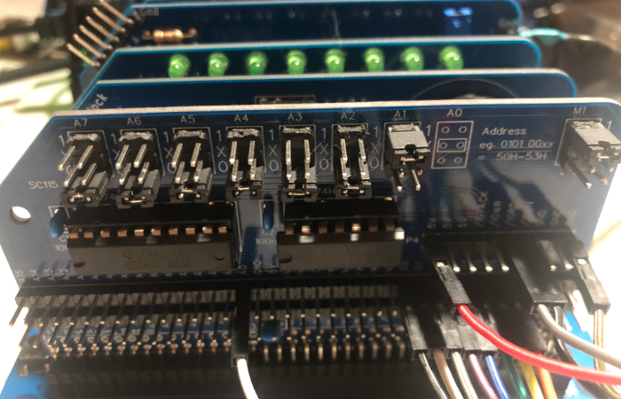
As you can see in the image, my jumpers are set to 0000001X. With this jumper setting, the only ports we have available are 2, and 3. This is all we need. Port 2 will be our command port. Likewise, Port 3 will be the data port.
Make Your Connections
On the LCD, Pin 1 will be 5 volts, and pin 2 is ground. We can take this voltage directly from our prototyping board. Usually, there is no need for an extra power supply. Pin 3 is for the contrast adjust. I just put a 10K pot between GND, and Pin 3. Obviously, one of those connections go to the wiper of the pot. I left one pin of the pot floating. The Potentiometer simply adjusts the resistance to ground. We’ll talk about pins 4, 5, and 6 in the next section. This will be for our register select, Read/Write, and Enable. Let’s skip these for now, and hook up the data lines. D0-D7 on the prototype module connects to D0-D7 on the LCD module.
Finally, we need to supply power for the LCD Backlight. Pin 15 connects to 5v, and Pin 16 to ground.
Control Pins
At this point, we’ll connect pins 4, 5, and 6.
Register Select
Pin 4 is the register select pin. We’ll simply connect this to A0 on the prototyping module. This effectively gives us 2 ports that we can write to. When A0 is low, our address is even, and we are writing to the Command Register on the LCD. Likewise, when A0 is High, we are writing to the data register. Since our 688 is decoding the address as 0000001X, this gives us Port 2 as the command register (00000010), and port 3 as the data register (00000011).
Read / Write
Pin 5 is the Read/Write pin. This needs to be low for write, and high for read. If you are just writing data, then you can connect this to ground. If you will also read from the LCD, then you need to use the /IO Read pin, and invert it. I tried this with /IO Write directly, but this fell to zero too late, and I had no data on the display. You can invert this with a NOT gate, or NAND gate. In this case, I just used the 74HCT00N, and tied two inputs together. The two inputs connect to /IO Read. The output of the gate connects to pin 5. You can read about the NAND gate, and get it’s pinout here.
Enable
Lastly, we have Pin 6 on the LCD. This is the Enable pin. You can only read or write to the LCD when the enable pin is high. When it goes low, your text still stays on the display. For this pin, I just inverted the /IO Enable from the Prototyping module. Again, you can use a NOT inverter, or NAND gate. Since the 74HCT00N has six gates, you can just use a different gate on the same IC.
Initialize the Display for Using an LCD on RC2014
To initialize the display, I looked at how Ben Eater initialized his for the 6502, and applied the same concept here to the RC2014. Basically, we just write the following codes to the command register: 56 14 06 01 (These are in decimal). 56 sets the mode to 2 line display, 8 data bits, and 5×8 font size. 14 turns on the display with a non-blinking cursor. 06 increments and shifts the cursor, and 01 clears the display. In MSBASIC, you would do this as follows:
OUT 2,56
OUT 2,14
OUT 2,06
OUT 2,01
Next, you are ready to start writing ASCII Data to port 3, which is the data port. For example, OUT 3,65 should give you an A. Remember that you are in BASIC, so we are using DECIMAL by default.
Writing Code
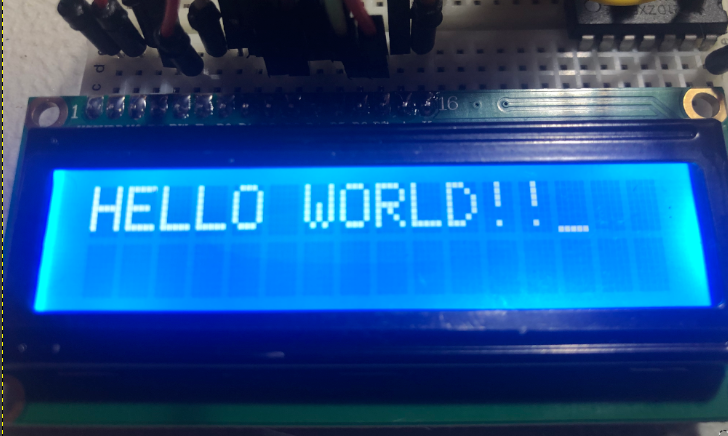
Here is my simple program to write “HELLO WORLD!!” onto the display:
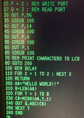
At last, your display should work!
For more information, visit the Vintage Computers Category Page!
— Ricky Bryce