
Introduction to Using Sensor Switches on the IMSAI 8080
Using Sensor Switches on the IMSAI 8080 allows you to give the operator a way to input data to your program. You can use these switches to trigger events, set a program operating mode, or to select different options. I’m running the IMSAI in Z80 mode, and I’ll be using the Z80ASM to compile the program. I’ll also show a way to get the status of the sensor switches in MBASIC.
If you don’t have the Z80ASM to run on the IMSAI, you can grab it from this link. Additionally, I’ll be using WordStar to build the program as a non-document file. It’s important to realize that in the examples below, I’m assuming the operator will only turn on one switch at a time. This is simply for the purpose of demonstrating the INput command. These examples will also demonstrate how to do branching based on a specific value of your switches.
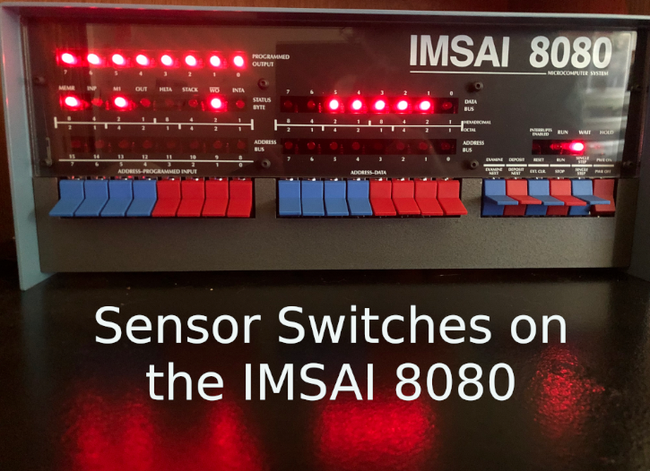
Basically, the sensor switches are the same as address/data switches 8 to 15. If you look at the bottom row of labels, you will see the sensor numbers 0 to 7.
Writing the program in Assembly
As I said before, I’ll be using WordStar to create this program as a non-document file. For future reference, I will store the file on the B: Drive, and it’s name is SENSORS.Z80. In Assembly, we use the IN instruction to get the status of our switches. Keep in mind the switches are on port 255 (decimal), or FF (hexadecimal).
Don’t forget that the lights are all backwards. In other words, when we send a 1 to a light, it shuts off. Zero turns it on. In this case, our logic is simple. In reality, you can write complex functions that execute when the operator turns on a switch.
    ORG 0100H     ; Program lives at 0100H because it's under CP/M.
INIT:             ; Label for program initialization.
    LD A,0        ; Initialize the accumulator to 0.
    LD B,0        ; Initialize the B register to 0.
    LD C,255      ; We'll be using C for our ports, which is 255.
    OUT (C),C     ; Send 255 to the LED's to shut them all off.
BEGIN:            ; Label for the beginning of our program.
    IN A,(C)      ; Get the status of the switches.
    CP 1          ; Compare the switches against 1 (A - Compare Value).
    JP Z,SWZERO   ; If A is 1, then 1-1=0, so we jump to the SWZERO Label.
    CP 2          ; Compare the switches against the value of 2.
    JP Z,SWONE    ; If A is 2, then switch one is on.  Jump to the SWONE Label.
    CP 4          ; Compare A against 4.
    JP Z,SWTWO    ; If A is 4, then switch two is on.  Jump to the SWTWO Label.
    CP 128        ; Compare A against 128.
    JP Z,SWSEVEN  ; If switch 7 is on, then our value is 128.  Jump to SWSEVEN Label.
    CP 0          ; Check for no switches.
    JP Z,NOSWITCH ; If no switches, then jump to NOSWITCH Label.
    JP BEGIN      ; Jump to the beginning to check for more inputs.
SWZERO:           ; SWZERO Label.
    LD A,1        ; Load 1 into the accumulator.
    CPL           ; Compliment the accumulator, flipping all bits.
    OUT (C),A     ; Turn on Light 0.
    JP BEGIN      ; Jump to beginning to continue.
SWONE:            ; SWONE Label.
    LD A,2        ; Load 2 into the A register (accumulator)
    CPL           ; Compliment the accumulator, flipping all bits.
    OUT (C),A     ; turn on light 2.
    JP BEGIN      ; Jump back up to the BEGIN Label.
SWTWO:            ; SWTWO Label
    LD A,4        ; Load 4 into the accumulator.
    CPL           ; Compliment the accumulator, reversing all bits.
    OUT (C),A     ; Turn on light #2.
    JP BEGIN      ; Jump to the begin label.
SWSEVEN:          ; SWSEVEN Label.
    CALL 0        ; Restart CP/M (exiting this program).
NOSWITCH:         ; NOSWITCH Label.
    LD A,0        ; Load 0 into the A register.
    CPL           ; Compliment the accumulator, flipping all bits.
    OUT (C),A     ; Shut off all lights (sends 255 to the LED's).
    LD A,0        ; Load the accumulator with zero.
    JP BEGIN      ; Jump to the BEGIN Label.
    END           ; End of this program.
At this point, we’ll press CTRL-K, then CTRL-X to save our document and exit WordStar.
To assemble our program, I’ll simply type Z80ASM SENSORS.BBB/F. Remember the .Z80 extension is implied. The “.BBB” is for our drive letters. First, our file is on drive B. Secondly, we are storing the COM file on drive, B. Thirdly, we want the list file on drive B. This list file is useful when troubleshooting. Our “/F” indicates that we want a full listing.
Simply type B:SENSORS to run our program.
Writing the program in BASIC
BASIC is another common language to write programs in the Z80. Let’s take a look at how we would write this:
10 REM SENSOR SWITCH TEST
20 OUT C,B
30 LET B = 0
40 LET C = 255
50 OUT C,C
60 LET A = INP(C)
70 IF A = 1 THEN GOSUB 150
80 IF A = 2 THEN GOSUB 220
90 IF A = 4 THEN GOSUB 270
100 IF A = 0 THEN GOSUB 320
110 IF A = 128 THEN END
120 LET A = 0
130 LET B = 0
140 GOTO 60
150 REM ENERGIZE LIGHT 0
160 LET A = 1
170 LET B = A XOR 255
180 OUT C,B
190 LET B = 0
200 LET A = 0
210 RETURN
220 REM ENERGIZE LIGHT 1
230 LET A = 2
240 LET B = A XOR 255
250 OUT C,B
260 RETURN
270 REM ENERGIZE LIGHT 2
280 LET A = 4
290 LET B = A XOR 255
300 OUT C,B
310 RETURN
320 LET A = 0
330 LET B = A XOR 255
340 OUT C,B
350 RETURN
360 END
Basically, we’re just doing the same thing we did in the assembly example above. You can use this logic, then modify your code to make a part of your program execute when the operator provides input. Here, we are only using switches 0, 1, 2, and 7. You can add different functions to this program for the other switches, or even use a combination of switches to trigger certain subroutines in your code. If you need to use a combination of switches, simply figure out what the decimal value will be for the combination of switches the operator needs to turn on. Use this number as the compare value.
For more information, visit the IMSAI Category Page!
— Ricky Bryce