
Introduction to Optocouplers and Optoisolators
Basically, we use optocouplers and optoisolators to minimize interference in our control circuit. We separate the load side of the circuit from the control side. In other words, we don’t need to worry about noise from the load interfering with the control circuit. Additionally, this provides some form of protection of the microcontroller from incorrect wiring, and failures, such as short circuits.
Anyone who has spent some time with microcontrollers has probably seen some strange things happen due to a noisy load. This is especially true with inductive loads, such as a relay coil, or a solenoid. The optocoupler does not eliminate the need for a flyback diode or snubber for inductive loads, but it does help to keep most all of the noise out of your control circuit. Depending on the optocoupler you choose, you might also eliminate the need for an extra transistor to control larger loads. Optocouplers are available for switching DC as well as AC loads.
Although there are many different types of optocouplers, this example will use the 4n35. We will turn on a simple LED through the optocoupler
Description of Operation
The control circuit simply turns on an LED which is inside of the optocoupler. This light, in turn, causes the photo transistor to conduct on the load side. We still need to take the regular precautions to ensure we do not exceed the load limitations of the microprocessor, or the optocoupler. For more information on the 4N35, check out the datasheet.
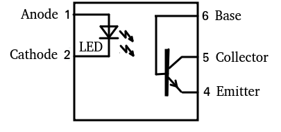
4N35 Optocoupler Pinout

In this case, our control circuit connects to the left side (Pins 1&2). Likewise, the Load circuit connects to the right side (Pins 4&5). We make no connection to pin 3. At the same time, we do not need to make a connection to the base (pin 6) since we are controlling the photo transistor with the internal LED.
Wiring the Optocouplers and Optoisolators
I’ve created the following diagram using Tinkercad. In this case, I’ll just use a simple push button to represent an output from the microprocessor. This will simply the operation of our circuit so we concentrate solely on how the optocoupler is working.
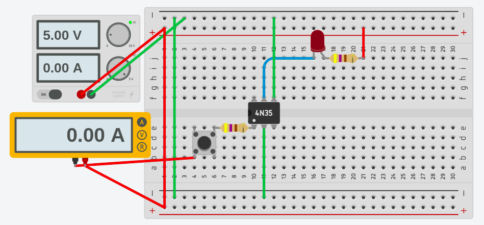
Remember, pins 1&2 are simply an LED, and we treat them as such. Therefore, we need to add a current limiting resistor in series with the LED.
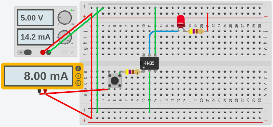
When we press the button, the LED turns on inside of the optocoupler. In turn, this causes the Phototransistor to conduct. The red LED acts as our load, and this LED will energize.
For more information on other components, visit the beginner’s category page!
— Ricky Bryce