
Introduction to the MAX232 for RS232 Communication
In this section, we’ll set up a MAX232 for RS232 Communication. The MAX232 converts TTL, such as data from a microprocessor, to RS232. We power the MAX232 with 5V, then use charge pumps to increase the voltage for RS232. The charge pumps are simply capacitors the chip places in parallel to charge, and in series to send an RS232 signal. RS232 has been around since 1960. Over the years, it’s been used in a very wide variety of applications.
For this post, I’ll use the MAX232EPE. This is similar to the MAX232CPE. You will want to consult the datasheet for your particular variation of this IC to get the exact specifications, and wiring diagram. Keep in mind that you can always purchase a module that already has the charge pumps and serial port. In this post, however, we’ll set it up from scratch. It’s important to realize the maximum distance is 50′. However, this maximum distance will vary based on your application.
Generally, RS232 is for point to point communication. On the other hand, there is a master-slave method which will allow communication to multiple devices.
Charge Pumps
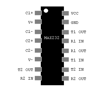
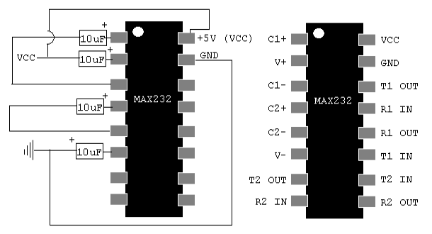
For the charge pumps on this particular MAX232 IC, I’ll use four capacitors. These are 10uF/50V each. As can be seen by the labels on the pinout, we already know where two of the capacitors belong. Connect the first capacitor between pins 1 and 3. Since I’m using electrolytic capacitors, the polarity is important. Plus goes to pin 1.
Likewise, connect the second capacitor to pins 4 and 5. (Pin 4 is positive).
Thirdly, connect a capacitor between V+ (Pin 2), and VCC. Pin 2 is plus. Finally, the last capacitor connects between V- (Pin 6) and GND. (GND being Plus!).
While we’re at it, we might as well go ahead and hook up VCC to +5V, and GND to GND.
** It’s important to realize that some diagrams I’ve seen use 1uF capacitors. You can place an additional 10uF capacitor between VCC and GND, VCC being + of course. Check the manufacturer’s recommendation for your exact MAX232 IC.
Connect to the Microcontroller
If you have a 5v microcontroller, this will be a direct connection. However, if your microcontroller runs a different voltage, such as 3.3v, you might consider a logic level converter. You only need 3 simple connections. R1 OUT on the MAX232 connects to the receive pin on your microcontroller. T1 IN connects to the Transmit pin. Also, don’t forget to connect the ground on your microcontroller to the same ground on the MAX232.
Pinout of 9-pin D-Shell
On the 9-Pin D-Shell simply connect pin 2 to transmit, pin 3 to receive, and pin 5 to GND.
That’s it! Your ready to start sending data over RS232. Depending on the device you are connecting to, you may need a null modem adapter. Another option is to swap pins 2&3 on the D-Shell connector. If you look very closely at your D-Shell connector, under the right light, the pins should be numbered. Sometimes, they are very difficult to read.
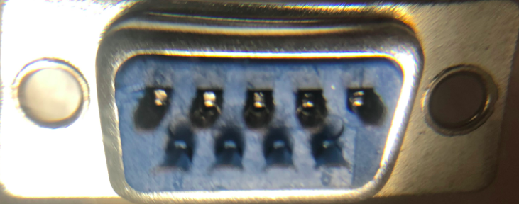
Here is the back of a male connector. Under a magnifying lens, you can barely make out the 1 and 5 on the top row, and 6 to 9 on the bottom row. 9 is right under 5.
For more information on basic projects, visit the beginner’s category page!
— Ricky Bryce