
PLC-5 Latch Vs Seal
There are a few differences in the PLC-5 Latch Vs Seal. In this section, I’ll explain the operating of each type, and some dangers associated with both methods.
Always be very careful when making any changes to the PLC program. Undoubtedly, you will want to get approval before implementing any change. You might not realize the affect on other areas of operation. Furthermore, a change might affect various modes of operation differently. For in-depth instruction help, you can check out the PLC-5 Instruction Set Reference Manual.
Latching
The latch instruction simply writes the value of 1 to a data table. Basically, when the latch goes false, the bit will remain high unless another part of your project, HMI, or another processor shuts it off. Keep in mind that the latch is retentive. In other words, if the processor looses power, then powers back up, the latch is still on. Even when the processor goes to program mode, then back to run, the latch is still retentive. On the other hand, if the energy storage unit is low, and you power off, you might loose the whole program.
Let’s take a look at a latch/unlatch pair. We’ll assume I’m actually online with the processor.
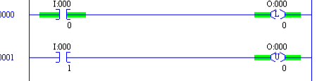
Notice that when switch 0 goes true (I:000/0), the latch bit is energized. The fact that it’s energize also reflects in rung 1 on the unlatch. This is how latch and unlatch works in the SLC-500, PLC-5, and ControlLogix.
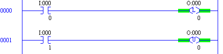
What’s more is that when switch 0 shuts off, the latched bit is still true.
Of course if I energize switch 1, in the bottom rung, the output shuts off.
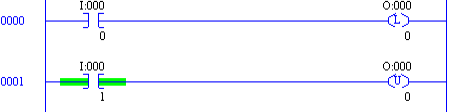
As you can see, the fact that the output bit is de-energize reflects on both rungs.
Seal Circuit
The Seal Circuit is what you would generally think of as a motor starter circuit. One difference between the latch and seal is that when the processor boots, the seal will break, and the output will shut off unless the logic has another path to energize the output.
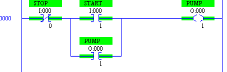
Let’s take a close look at a standard seal circuit. For simplicity, we’ll assume that both the physical start and stop push buttons are wired as normally open.
To begin with, there is no path to energize the output, so the pump is off in this example.
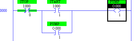
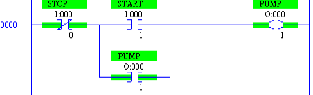
Now you will see what happens when we press the start button.
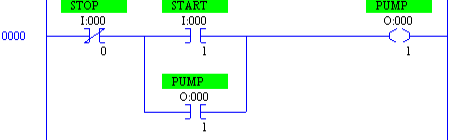
The pump will run because it has a path, but look at the instruction just beneath the start button. This instruction has the same address as the output. Therefore when the output goes true, the lower branch goes true. This means that when we release the start button, the output still has a path to stay energized.
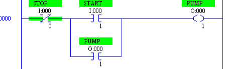
Lastly, to break the seal, we need to change the state of the stop button. Once this happens, the output shuts off, and so does the seal branch.
As you can see, when we let off of the stop button, the first instruction goes true, being an XIO instruction. The circuit is now waiting for the start command again.
Summary of PLC-5 Latch Vs Seal
To sum it up, the latch is good for applications where you need the processor to remember it’s last state. Be careful, though, because this could cause unpredictable movement on startup. Use a seal circuit where you need the logic to reset when the processor boots. Both methods, however only require a simple pulse for the output to go to an on state or an off state.
For other information on the PLC-5, visit the PLC-5 Category page!
— Ricky Bryce