Introduction to Interlock Bits (Internal Bits)
If you are not familiar with basic instructions yet, please visit the post on how basic logic works.
Interlock bits are tags in the processor that represent the fact that a certain condition has been made. For example: If all guard gates are shut, we would set a single BOOL bit that represent this condition. Another example is for emergency stops. Emergency stop switches will drop control power for safety, but there might also be a second contact block. This second set of contacts will inform the processor of which emergency stop has been pressed.
In this example, we will have two pumps that are energized with two switches. We don’t want the pumps to run, though if a guard door is open. We will have four guard doors, and as long as all of the guard doors are shut, the pumps can run. The reason to use these interlock bits is to save time and memory. This will also simplify our logic for troubleshooting.
Imagine if we have 15 guard doors, and 20 pumps. You wouldn’t want to add all 15 guard door switches to the logic for each of the pumps. Instead, all of the guard doors can turn on an internal bit. This bit represents the fact that all of the guard doors are shut. Then, we can just use that one bit to prevent our pumps from starting if one of the guard doors are open.
Ladder Logic
Before starting, let’s create a BOOL bit that we can use in logic as an internal memory location. As a rule of thumb, I always try to name the bits in the true state. This makes troubleshooting logic much easier later on. To create the bit, go to your controller tag database, and we will be in “Edit Tags”. If you are offline, (or in REM mode), you should have a blank line at the bottom to add our tag.
Let’s name the tag “Guard Doors Shut”.

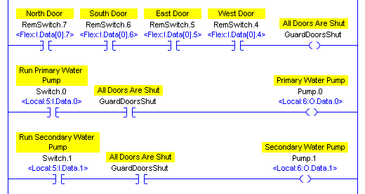
Next, Let’s write a line of logic that will turn on this bit if four guard doors are shut.

Now, we’ll add a couple more rungs of logic that depend on the guard doors to be shut before the outputs will energize:

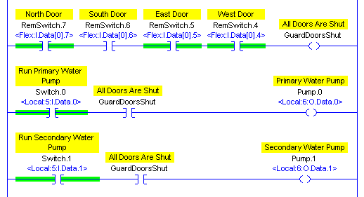
Now, Let’s try this in the processor. As long as all of the guard doors are shut, the pump can run.

Notice what happens though, if one of the guard doors are open.

Just by one door being open, this will shut off our interlock bit. Then the “GuardDoorsShut” bit is shut off, this will interrupt our outputs, so we no longer have a path to energize our pumps, and our pumps will shut off.
The purpose of this post is for you to understand the basic fundamentals of Interlock bits. If this was a real-life situation, our logic would be written in such a way that the pumps might not start as soon as a door is shut. You might have a time delay, or the pumps would use seal circuits to ensure the pump is not continuously starting and stopping if a guard door was swinging open and shut. If we used the guard doors to break the seal, then the operator would be required to manually energize a pump once the guard doors are shut.
— Ricky Bryce
