Introduction to ControlLogix Motion Control
In a ControlLogix Motion Control system, you will usually have a module in the chassis that communicates with motion drives. The drives are connected to servo motors. The purpose of a motion system is to provide precise movement. The drive is always commanding a motor to move in a certain direction. The encoder will tell the drive it’s actual position. Servo motors will typically have a high value of torque in order to hold their position once the desired position is achieved.
Examples of drives include the Kinetix 6000 (which runs on a SERCOS (fiber optic) ring), and another modern example would be a Kinetix 6500 (which runs on an Ethernet Network)
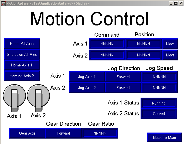
Here is an example of a screen we build in class.

Each drive in a servo system is called an “Axis”. The Axis will usually consist of a servo motor, and feedback from an encoder. Each drive could also have an “Auxiliary Axis” to which a separate encoder is attached. An example of this might be for precise timing of servo movement based on the position of another part of the machine.
Examples:
An example of servo use might be in a machine that performs boxing of a product. One servo might control the horizontal axis of a pickup arm, and another servo might control the vertical axis. The horizontal axis will move a pickup arm to a specific location, and another axis might move the pickup arm up or down. Servos can also be used to close the lid on a box, and glue the box once the product is inside.
Another example of a servo would be to control the pitch of a knife when cutting a product, such as a design. One servo axis could control the location of the knife, and another servo could be used to turn the knife blade (so it’s not cutting a product sideways).
What’s to come!
In the documentation of this category, we will learn how to set up a motion group. We will then add axis to the motion group, and issue motion direct commands. We will then use logic to control the rotation and position of the servo axis.
Move onto the next document on creating a new motion project!
— Ricky Bryce

Pingback: Creating a Virtual Axis in the ControlLogix processor
How to use MAPC command for control master and slave axis in vertical ball screw load and they have to synchronize always (can’t desynchronize) ?
I’m not sure of your exact application, but there are a few steps involved in using the MAPC, and creating a CAM profile. You might want to check out this video: https://www.youtube.com/watch?v=1POMGsA9LZY You can go back and look at parts 1, 2, and 3 if you want to see how he built up to that point. In that video, he walks you through how to set up the MAPC, and cam profile.
If all you need is simple gearing on a linear scale, though, the MAG is very simple to use. Just realize the axis “ungear” when they are shut down, so you would want to get the axis in the position you want them before executing the MAG.