Introduction to the MK-328
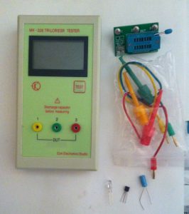
Today, a new meter arrived in the mail. This is the MK-328. I’m very impressed with this meter for $17 on Ebay! The meter will test many components such as diodes, LED’s, transistors, triacs, capacitors, resistors, MOSFETS, etc.
At first, I was skeptical. For such a low price, I was worried about the accuracy. After the first few tests, though, I was very impressed.
When buying some electronic parts on Ebay, I’m always questioning whether the parts are fake or real. Sometimes I even question whether the parts, such as MOSFETS will even work at all. It’s very frustrating to put a project together, then to spend a huge amount of time troubleshooting troubleshooting parts that are not meeting the required specifications.
LED Test
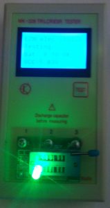
In my first test, I checked out a simple LED. My meter came with a “jig”
that I can plug in to easily test the parts. I placed the “Jig” on the meter, and inserted the LED. Then I pressed the “TEST” button.
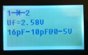
It did not matter which way I inserted the LED. Even though the LED is polarized, the MK-328 seemed to figure everything out just fine.
After the test was complete, the results displayed on the screen.
The meter correctly showed the “Cathode” was connected to pin 1 of the meter. The forward voltage is 2.58 volts. The meter even gave a readout of the LED’s Capacitance!
Capacitor Test
In this test, I removed the LED, and I inserted an electrolytic capacitor. Remember Electrolytic capacitors are polarized. When I ran the test, the results appeared as follows:
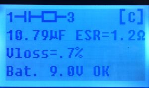
This was a 10 MicroFarad capacitor, and it’s reading about 10.79, which is within 10% tolerance. The ESR measurement is the Equivalent Series Resistance. In this case, we have 1.2 Ohms. The MK-328 even shows the voltage loss of .7%!
Transistor test
This was the test I was excited about. Different series of transistors have different pinouts. The transistor is difficult to see in this image, but I placed the transistor in the meter as shown.
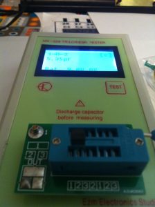
Again, the pinout does not matter as long as the three leads of the transistor are placed across the first three columns of the “jig”. Here was the result.
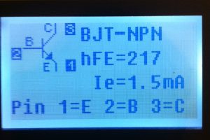
As you can see, the meter correctly identified the transistor as an NPN. The hFE is the gain factor of the transistor. In this case 217. The pin (of the transistor) that I connected to Pin 1 of the meter is the Emitter, 2 is the Base, and 3 is the collector.
For the price and capabilities of this meter, I am very pleased, and I don’t know how I ever got along without this meter in the lab!
— Ricky Bryce

Pingback: Mega328 Meter to test ESR< Capacitance, Inductance, Transistors, etc.
Pingback: Usage of Transistors, examples, applications, and a sample circuit.
Pingback: DSO150 Oscilloscope -- Overview of assembly, and review of operation.
Does it do in circuit capacitor esr testing?
Yes Sir! If you look under the Capacitor Test, you will see that it displays the ESR!
Does it do in circuit esr test though that is the acid test?
I’m not sure I would trust this meter with in-circuit testing without checking it against a high quality ESR meter first. This meter cannot obviously compete against professional meters. When building projects, I use it to check some of the components just to make sure I didn’t read them wrong, or that they are not fake knock-offs. You would be surprised with some of the junk that comes out of China. Haha