Introduction to SLC to ControlLogix Messaging
SLC to ControlLogix Messaging might be easier than you think. For example, the SLC 5/05 will take 5 integers from the N10 data file, and send those 10 integers to the Allen Bradley ControlLogix processor.
The ControlLogix does not have the same addressing structure as the SLC 500. We need to map the SLC Initiated messages to an array in the tag database.
This diagram will show an example of our goal in this post. Remember, this post is just for example only. Keep in mind that any time you download, your processor will stop executing logic.
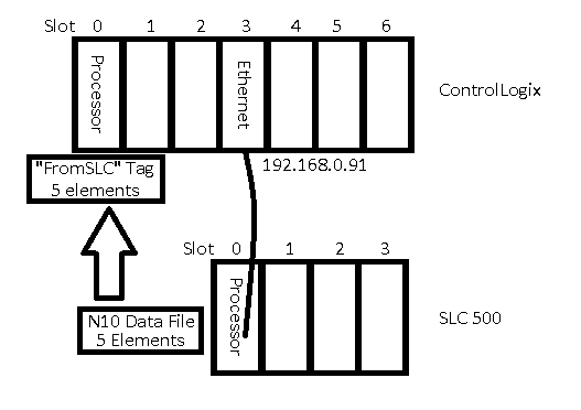
ControlLogix Mapping
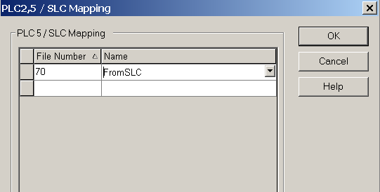
Since the ControlLogix has a different addressing structure than the SLC, we must map the SLC message to an array in our tag database. For this example, I will pick an arbitrary file number (70). Later on, the SLC will “think” it’s sending data to another SLC Processor, and storing that data to N70:0 to N70:4. In the ControlLogix, we must map this request to an array of integers.
First, we will create an array called “FromSLC” in our Controller Tag Database. This will be 5 Integers.

Next, click on Logic / Map PLC/SLC Messages.
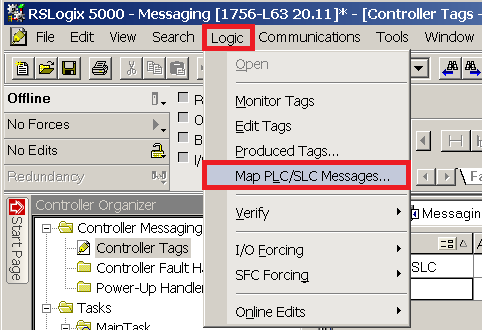
Then, map file #70 to the array we just created… “From SLC”.
Then Download to the ControlLogix Processor.
Setting up the SLC Data Files
First, we need to create a control file for the Message instruction to be able to operate. To do this, we’ll right click the Data Files folder, and create a new data file.
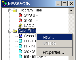
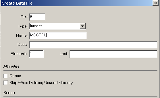
This will be file #9 (Integer), and we’ll name this file “MGCTRL”. Since we are writing this logic offline, the file will expand automatically when we verify or download the project.
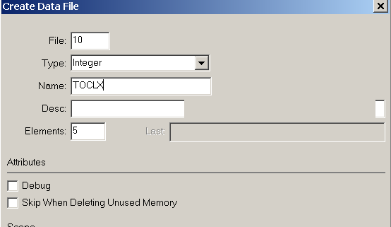
Now, we need to create the data file that will be transferred to the ControlLogix. We will make this file 10 (Integer), and it will be 5 elements long. We will just name this file “TOCLX”.

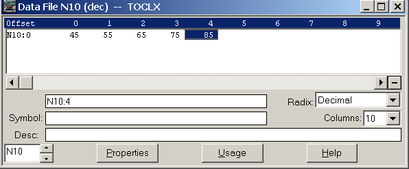
Normally, our logic would populate this data file with information that is being sent to the ControlLogix. For this example, I’ll just type in 5 random numbers.
Writing the SLC Logic
The message instruction needs to be triggered with a pulse. Each time the pulse is generated, the MSG instruction will execute. The message will be a Peer to Peer write, and the control block is N9:0. I set up my logic as follows:
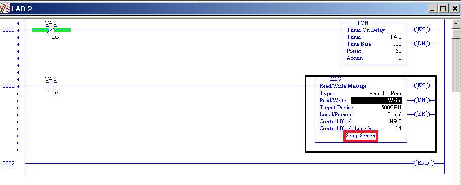
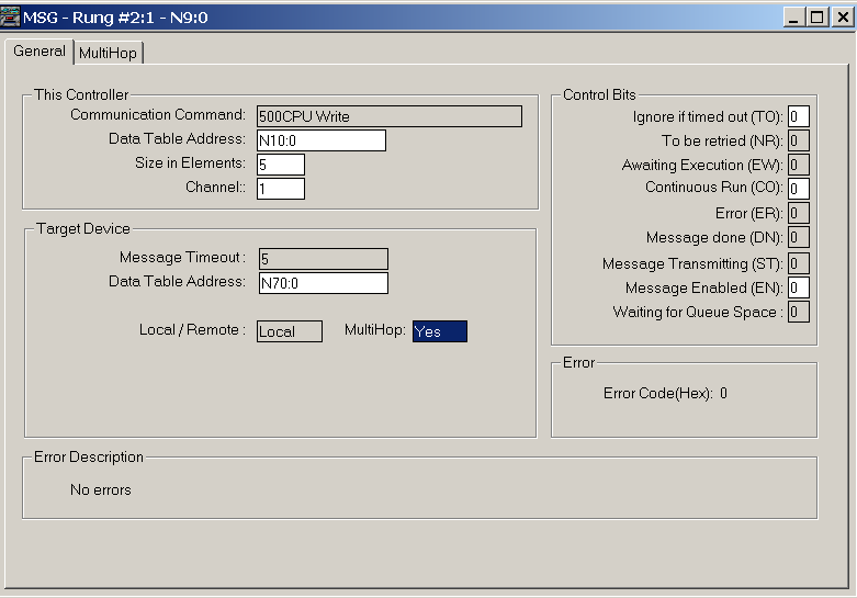
Next click on “Setup Screen” within the MSG instruction. Remember, we are taking 5 elements from N10:0, and transferring the data to the ControlLogix processor (N70). Be sure to turn on the “MultiHop” Feature. Our message will be sent out of channel 1 of the 5/05 (Ethernet).
Next, I went to the “Multihop” tab, and set up the hops as follows:

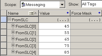
At this point, download to the SLC, and test your work. When I go back to the ControlLogix processor, I can see that I’m receiving the data that I placed into the N10 file in the SLC.
Summary of SLC to ControlLogix Messaging
In short, there are only a few things to do to get SLC to ControlLogix messaging to work. First, we need to initiate a message in the SLC. Keep in mind, the SLC “thinks” it’s sending a message to another SLC. Basically, we just pick an unused files number in the target such as N70. Over in the ControlLogix, we need to map this file number to an array that you create. We do this by going to Logic | Mapping. You may need to be offline to set this, then download. The ControlLogix requires no other configuration. Using this method, the SLC can read or write data to the ControlLogix.
Note on 5/04 Processors
If you are using the 5/04 SLC processor, this uses DH+ Natively. As long as the ControlLogix processor is in slot 0, the default setup of the DHRIO module in the ControlLogix chassis should work fine. The SLC would just send data to the DHRIO module. On the other hand, if your processor is in a different slot, just configure the DHRIO module using RSWho in RSLinx. You can configure the DHRIO module so it knows the slot number your processor is in. When the DHRIO receives a message from a 5/04, it will then pass that data to the processor.
If you are interested in learning about ControlLogix to ControlLogix, messaging, visit the ControlLogix Messaging Page.
— Ricky Bryce

Can you use a read instead of write in this situation?
There is no problem with doing a read as well. In fact, when practical, it’s usually better to do a read for troubleshooting purposes. When a person is troubleshooting a problem from Outputs back to the source, they can cross reference a data file that will trace back to the message read instruction to see where the data is coming from. When another processor is writing, it’s more difficult to trace where data is coming from in the processor that is being written to (without documenting this in the project). Sometimes, a message write is more practical, though, to limit bandwidth, and write a message only when a change in data occurs.