
Introduction to the 74CH93 Binary Counter
The 74CH93 Binary Counter has several uses. In the first place, you might use the counter as a divider. In this case, you can divide counts by 2, 4 or 8 for use with lower frequency devices. Additionally, you can use it to provide on/off signals using a single push button. Another fun use would be to make your own binary clock.
Description of Operation
The 74CH93 Binary Counter has 4 outputs (0-3). One mode simply toggles bit 0 on and off for each false to true transition of clock 0. Additionally, you have a second clock input (clock 1) which also uses outputs 1 to 3 to count in binary. This would give you a count of 0 to 7.
On the other hand, if you connect clock 1 to output 0, all four bits will give you a binary count. In this case, you can count from 0 to 15 in binary by toggling clock 0.
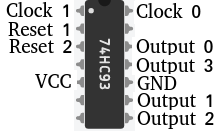
Pinout and Wiring for the 74HC Binary Counter
This example will show both “Modes” that I have described above. Let’s take a look at the pinout. I’ve used the example here on Tinkercad. Be sure you verify the pinout of the specific IC that you have.
To begin with, let’s connect out 5V supply to VCC and GND. Reset 1, and Reset 2 will also connect to GND.
Each output will connect to an LED through a current limiting resistor.
We’ll connect a push button to clock 0. When the button is released, a 10K pull down resistor connecs clock 0 to GND.
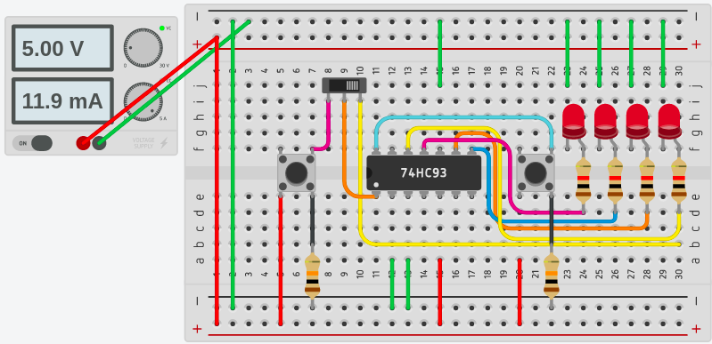
Finally, we’ll have a switch. In one position, the switch connects Clock 1 to Output 0. In the other position, the switch connects Clock 1 to a second pushbutton. When this push button is released, again, Clock 1 connects to ground through a 10K pull down resistor.
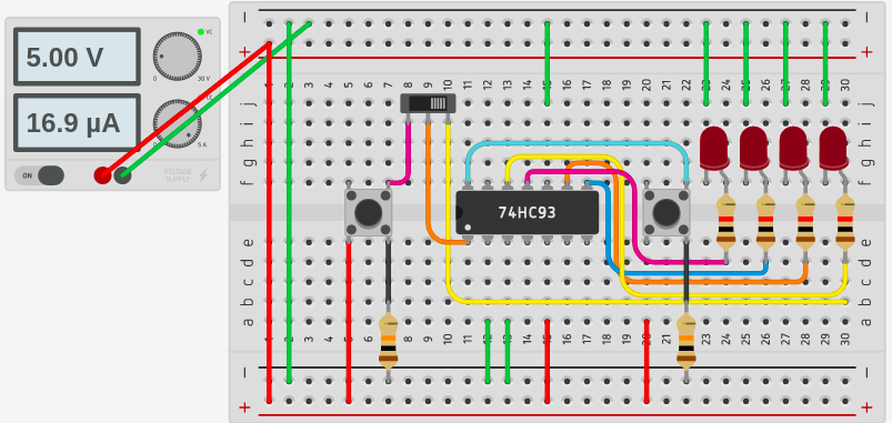
At this time, we’ll test our work. As long as the switch connects clock 1 to Output 0, we will use the push button for clock 0.
Single Clock Input
As you can see, each time the push button is pressed, our LED’s will give us a true binary count from 0 to 15.
Separate Clock Inputs
On the other hand, if we move the switch, clock 1 disconnects from output 0. Clock 1 connects to another push button. This gives us a second input. In this case. the push button on clock 1 us a binary count on outputs 1 to 3. Output 0 simply toggles on and off, and changes state for each false to true transition of clock 0.
For other simple projects, visit the arduino beginner page!
— Ricky Bryce