
ATTiny85 Overview —
In some projects, we don’t need the amount of I/O that is supplies with the Atmega 328 MCU, so we can use a cheaper alternative…. The ATTiny85! In many projects, space can be limited as well, but this little processor does a great job! We have 5 I/O pins available for use, a reset, VCC, and GND. Because there is not as much capability as an Atmega 328, it can be a little more challenging to program, though.
In this document, we will make the connections and program the ATTiny 85 with a USBtinyISP programmer.
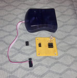
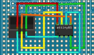
For this example, I’ve used prototype paper, an ISP header, and an 8-pin socket to build my own board to program the ATTiny 85. The wiring for this programming board is as follows: (diagram created with Fritzing)
Step 1 — Install the ATTiny 85 Board
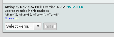
Before we program the processor, we need to add the board into our Arduino IDE. To do this, we will click on File | Preferences, and add the following URL to the boards manager.
https://raw.githubusercontent.com/damellis/attiny/ide-1.6.x-boards-manager/package_damellis_attiny_index.json
Now go to Tools | Boards | Boards manager. If you scroll to the bottom of the list, you should see the ATTiny boards that you can install.
Step 2 — Select the ATTiny 85 board
Under Tools | Boards, select the ATTiny boards.
Under Tools | Processor, select the ATTiny 85
As long as you didn’t change the processor’s clock speed, we will leave this speed at default (1 MHz) for this example.
Step 3 — Upload your program
In this example, we are using the USBtinyISP programmer, so we will go to Tools | Programmer, and choose USBtinyISP
If you are using the blink program as an example, you can change the digital output to pin #2 for testing.
Click Sketch | Upload using programmer
You are now ready to remove the ATTiny 85, and place it in on the breadboard, or in your circuit!
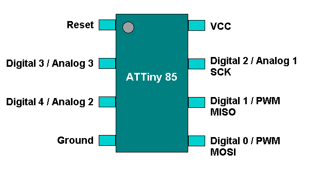
You must take the RESET pin LOW to reset the processor. Pins 5 and 6 (Digital 0 and 1) will also support PWM, and pins 7, 2, and 3 are for analog 1, 3 and 2 respectively. For the size and the price, I’ve been amazed with this small MCU, and hope you enjoy experimenting with it too!
— Ricky Bryce
Thanks.
I need to use 4 output as digital. how can I set 4 digital as output with that model?
1 is for analog.
You have 5 digital-capable input/output pins… but some of them can be Analog INSTEAD. Only two could be PWM output (need to drive servos?). Or you can use three pins for SPI… your sketch just needs to decide which mode those pins will be.