
Introduction:
One of the most frustrating things for beginners is working with firmware. There are many flash utilities available and many different firmware types and revisions that you can flash. Here we will flash the ESP8266-12F. Use this document at your own risk, and make sure you are familiar with working with electricity and electronics (and all safety) before proceeding!
 For my projects, I like to use the AT firmware on the ESP8266. The AT commands can be used to connect to your access point, control I/O, and send data to a web server.
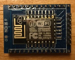
I recently purchased some ESP8266-12F modules, and needed to update the firmware to take advantage of the latest features, such as AT+CWIOWRITE to control the I/O.
The easiest utility I’ve found to work with is at this URL: (esp8266_flasher.exe)
Newer firmware can be downloaded from this link:
http://www.electrodragon.com/w/File:V2.0_AT_Firmware(ESP).zip
Wiring your module:
B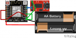 e sure you have a good 3.3v filtered power supply, and that all of your connections are solid. This is VERY important. In my case, I used a 2A 5v power supply with an LM1117 voltage regulator to reduce the voltage to 3.3v. I connected this supply directly to the ESP8266. Breadboard connections have a high resistance and can be unreliable. On the ESP8266-12F (with supernode board), I connected IO pin 0 to ground, 2 to 3.3v, and 15 to ground. I also used an FTDI programmer, and connected ground of the programmer directly to ground of ESP8266. TX on the FTDI programmer needs to connect to RX on the ESP8266, and RX on the FTDI programmer needs to connect to TX on the ESP8266. Don’t forget to connect the Chip Enable pin to 3.3v. If you soldered any headers yourself, also be sure that you have solid, proper connections!
Flashing the firmware:
 You will need to know on which COM port the FTDI programmer appears. You can get this COM port # from Device Manager.
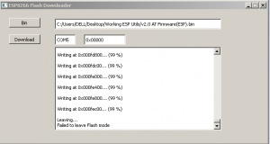
Run the esp8266_flasher.exe utility that you downloaded earlier. Click the “Bin” button to browse for the firmware binary that you downloaded. Be sure the ESP8266 is powered up, and press the Download button.
Now, you are ready to move I/O pin 0 to 3.3v and cycle power (or reset) the module.
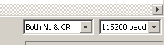 You can use the serial monitor of the Arduino IDE to verify the new firmware is working. In the Arduino IDE, select your COM port under “Tools” Then go to the Serial Monitor. In the bottom left corner of the Serial Monitor, I’m set up for both NL & CR with a baud rate of 115200.
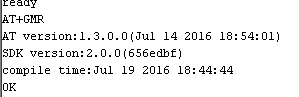 You can verify the new firmware by typing AT+GMR.
If you wish to connect to your access point, set the ESP8266 up as a station by typing AT+CWMODE=1
Then to enter your SSID and password: AT+CWJAP=”SSID”,”password”
— Ricky Bryce