
Introduction to Arduino Vape Box Mod
In this document, I will explain how I built my own arduino vape box mod. This box will be based on PWM (Pulse Width Modulation). Be aware that the purpose of the document is just to explain how I built my own box. There are many dangers associated with this, so you will want to research the dangers of the components, and apply your own safety features.
This mod uses Lithium batteries which can explode if used improperly, so I would always recommend using protected batteries. In this box, if the batteries are inserted improperly, the results could be disastrous. I’ve taken a few safety precautions on this box, though. You also would want to add safety features in the event that a MOSFET shorts and continuously fires.
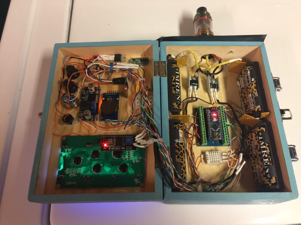
In my setup, I can read temperature, humidity, and barometric pressure. In addition, the box will act as my alarm clock, and garage door opener. To use the garage door opener, I’ve built another box which connects to my home wifi. This other box simply closes a relay for one second to simulate pressing the push button. The purpose of this document is simply to give you ideas. You assume all liability if you try to implement this. I’m just documenting the project here for my own reference.
List of Components:
All of these parts were not required just to make the vape box work by itself, but here is what I used:
Arduino IDE installed on your PC
1 x USB Mini cable (to connect PC to Arduino nano)
1 x painted wooden box
4 x Dual 18650 battery sleds
4 x 25A resettable fuses
2 x 3034 MOSFETS (With heatsinks) Beware of fake mosfets!
2 x 15K Resistors
1 x Arduino nano
1 x Screw terminal PCB for Arduino nano
1 x DC-DC Buck Converter (to regulate voltage to 5v)
1 x 1117 voltage regulator (required only to use the wifi card)
1 x ESP8266-01 (Flashed with AT firmware)
1 x DHT22 Temperature and Humidity Sensor
1 x BMP280 (Barometric pressure sensor
(Note — If using a BME 280, I would not have used the DHT22, because the BME will read both temperature and humidity)
1 x ZS-042 Real Time clock module. (For alarm feature) with charging circuit disabled.
1 x CR2032 battery
1 x 510 connector
1 x (20 x 4) LCD Display (with I2C)
2 x Maintained Pushbuttons (For control power and boost power)
2 x Small Momentary Push buttons (to adjust power level)
1 x Large Momentary Push button (Main Vape Button)
1 x Active Buzzer
1 x LED Voltmeter (Mine is rated 0 to 30 volts)
1 x PCB Switch (to turn the wifi card on or off for energy saving)
1 x Atomizer of your choice
8 x 18650 high drain batteries. All of these must be the same capacity, and have the same charge!
3′ of 16 Gauge Wire
2′ of 14 Gauge Wire
7′ Cat 5 cable (I removed all of the conductors to use as the control wiring)
Basic wiring Concepts:
This mod will run a max of 8.4 volts
Power Provision:
All of the individual battery sleds are wired in parallel. This means that all batteries will face the same direction. You must use protection. Don’t rely on yourself putting the batteries in the proper way every time. Use protected batteries. Only connect these batteries if you are familiar with how to safely design your own battery system. Don’t rely on the safety features I’ve provided in this document. Do your own research. You assume all responsibility if you implement this in any way!
Definitions: I’m defining a power pack as a sled of 2 batteries. I’m calling a power bank 2 power packs connected in series (ie. left side and right side) I’m calling the main power unit as both banks (left bank and right bank connected in parallel)
Left Battery bank: The lower left battery pack is connected in series to the upper left battery pack. Fuses are used to protect against reverse polarity, and overcurrent.
Right Battery bank: The lower right battery pack is connected in series to the upper right battery pack. Fuses are used to protect against reverse polarity, and over current.
Using 14 gauge wire, the entire left battery bank is connected in parallel to the entire right battery bank. (providing a total of 8.4 volts when fully charged. Fuses are used to protect against an overcurrent condition.
510 Connector: Using 14 gauge wire, the + side of the main power unit will connect to the center pin of the 510 connector. Using 16 gauge wire, the case of the 510 connector has two 16 gauge wires soldered to the connector. Each of these will go to the Drain (center pin or case) of the 3034 MOSFETS.
Control Power: The + of the main power unit will connect to one side of your maintained Power Switch. Coming out of the power switch, to the + (input) of the DC-DC Buck converter. I’ve used a 5A resettable fuse coming from the + of the main power unit. The – (input) of the Buck Converter will connect to the – of the main power unit. I’ve also jumpered the – of the Input and outputs of the buck converter together to ensure the commons are the same. Warning!!! If the – potential of the control circuits are at a different potential than the main power unit, the atomizer could fire at will!!!
If using wifi, we also need to connect the LM1117 voltage regulator to give us a 3.3v supply. The + output of the Buck Converter will connect to the small pcb switch, then from the switch to input of the voltage regulator (right pin) The – output of the buck converter will connect to the – of the voltage regulator (Left pin) and to the – of the ESP8266-01. The VCC (+) of the ESP8266-01 connects to the OUTPUT of the LM1117 (center pin) Daisy chain the + and – from the ESP8266 to the appropriate pins on the BMP280.
Powering all 5v devices: Connect the + and – of the buck converter to the appropriate pins of the DHT22, Arduino nano, LCD Display, and ZS-042 Real Time Clock.
Common Connections: The – of the Buck converter will connect to the remaining Maintained pushbutton (power boost), the small normally open buttons (for up/down power), the main vape button (large normally open button), the – of the voltmeter, and the – of the buzzer.
DHT22: Place a 10K resistor between VCC (left) and Data (2nd Pin). Connect the Data pin of the DHT22 to Digital pin 3 on the arduino.
Button connections: When the buttons are pressed, the following pins will become grounded on the Arduino Nano:
Main Vape Button – Pin 2
Reduce Power Button – Pin 4
Increase Power Button – Pin 5
Power Boost – Pin 11
Then the buzzer (+ side) will be connected to Pin 8
Firing Pin:
Be sure you have a 15K resistor connected across the left and right pins of each 3034 mosfet. This is a very critical connection. The mosfet will not shut off unless this resistor is connected!! Pin 10 of the Nano will connect to the gate (left pin) of both MOSFETs.
I2C Network: Connect pin A5 (SCL) of the arduino nano to the SCL Pins on the LCD Display, BMP280, and ZS-042 module. Pin A4 (SDA) will connect to the SDA Pins on these devices as well. You can just daisy chain from one device to another. If your cabling is long, you might need pullup resistors on these two busses. You can google the pullup resistors if you are having problems. I’m assuming your BMP280 is 5v tolerant for SCL and SCA. If your BMP280 is not 5v tolerant, you can use a logic level converter.
LED Voltmeter: We already have the – connected. On my voltmeter I have 3 leads. Ground… Then a red lead which powers the meter itself, and a yellow lead which measures the battery voltage. I connected the red lead to the + from the Buck converter, and the yellow lead to the + of the main power unit. If your voltmeter only has 2 leads, you can connect one lead to ground, and the other lead to the controlled side of your power switch. This way, the volt meter will not use any current when the power switch is off.
ESP8266: If using this feature, connect the RX of the ESP8266 to TX of the Nano. Connect the TX of the ESP8266 to the RX of the Nano. The CH_PD is connected to VCC to enable the module. I’m assuming the RX is 5v tolerant. If you are worried about damage to the ESP8266 though, you can use a logic level converter, or set up a voltage divider to ensure the RX pin does not receive more than 3.3v.
The Code:
#include <Wire.h>
#include <LiquidCrystal_I2C.h>
#include <SimpleDHT.h>
#include <LowPower.h>
#include “i2c.h”
#include “i2c_BMP280.h”
BMP280 bmp280;
LiquidCrystal_I2C lcd(0x3f,20,4);
SimpleDHT22 dht22;
//Define the pins
const int ButtonPin = 2;
const int pinDHT22 = 3;
const int DownPowerPin = 4;
const int UpPowerPin = 5;
const int FiringPin = 10;
const int BuzzerPin = 8;
const int PowerBoost = 11;
const int LedPin = 13;
// Discrete Variable Declarations
int ButtonState = 0;
int PowerBoostState = 0;
int BuzzerShutoffOK = 1;
int PowerLevelRaw = 50;
int PowerLevelScaled = 0;
int PowerSetting = 10;
int UpPowerValue = 1;
int DownPowerValue = 1;
// BMP280 Vars
float BMPtemperature;
float BMPpascal;
static float BMPmeters, BMPmetersold;
// Timers
unsigned long ButtonMillisStart = 0;
unsigned long ButtonMillisTimeout = 6000;
unsigned long FlashMillisStart = 0;
unsigned long FlashMillisTimeout = 100;
unsigned long SleepMillisStart = 0;
unsigned long SleepMillisTimeout = 300000;
int ButtonTimeout = 0;
int VapeTime = 0;
int VapeTimeLast = 0;
// Counters
int MyCounter = 0;
int LightCounter = 0;
// One Shots
int ButtonRising = 0;
int ButtonFalling = 0;
int UpPowerONS = 0;
int DownPowerONS = 0;
char LastSecond;
// This is for the Real Time Clock
#define DS3231_I2C_ADDRESS 0x68
// Convert normal decimal numbers to binary coded decimal
byte decToBcd(byte val){
return( (val/10*16) + (val%10) );
}
// Convert binary coded decimal to normal decimal numbers
byte bcdToDec(byte val){
return( (val/16*10) + (val%16) );
}
//—————————————-
void wakeUp()
{
// Just a handler for the pin interrupt.
}
//—————————————-
void setup() {
Wire.begin();
Serial.begin(9600);
//Serial.print(“Probe BMP280: “);
if (bmp280.initialize()){ //Serial.println(“BMP Sensor found”);
}
else
{
//Serial.println(“BMP Sensor missing”);
while (1) {}
}
// onetime-measure:
bmp280.setEnabled(0);
bmp280.triggerMeasurement();
//LCD Setup
lcd.init(); //initialize the lcd
// RTC
// set the initial time here:
// DS3231 seconds, minutes, hours, day, date, month, year
//setDS3231time(30,16,18,7,1,9,2017);
// Setup Pin Modes
pinMode(DownPowerPin, INPUT_PULLUP);
pinMode(UpPowerPin, INPUT_PULLUP);
pinMode(ButtonPin, INPUT_PULLUP);
pinMode(BuzzerPin, OUTPUT);
pinMode(PowerBoost, INPUT_PULLUP);
pinMode(LedPin, OUTPUT);
lcd.noBacklight();
//Configure Wireless
lcd.backlight();
lcd.setCursor(0,1);
lcd.print(“Setting Mode”);
Serial.println(“AT+CWMODE=1”);
delay(1000);
lcd.setCursor(0,1);
lcd.print(“Connecting Network”);
Serial.println(“AT+CWJAP=\”yourSSID\”,\”yourPASSWORD\””);
delay(3000);
}
// —————————————
// RTC Logic for Setting clock
// —————————————
void setDS3231time(byte second, byte minute, byte hour, byte dayOfWeek, byte
dayOfMonth, byte month, byte year){
// sets time and date data to DS3231
Wire.beginTransmission(DS3231_I2C_ADDRESS);
Wire.write(0); // set next input to start at the seconds register
Wire.write(decToBcd(second)); // set seconds
Wire.write(decToBcd(minute)); // set minutes
Wire.write(decToBcd(hour)); // set hours
Wire.write(decToBcd(dayOfWeek)); // set day of week (1=Sunday, 7=Saturday)
Wire.write(decToBcd(dayOfMonth)); // set date (1 to 31)
Wire.write(decToBcd(month)); // set month
Wire.write(decToBcd(year)); // set year (0 to 99)
Wire.endTransmission();
}
void readDS3231time(byte *second,
byte *minute,
byte *hour,
byte *dayOfWeek,
byte *dayOfMonth,
byte *month,
byte *year)
{
Wire.beginTransmission(DS3231_I2C_ADDRESS);
Wire.write(0); // set DS3231 register pointer to 00h
Wire.endTransmission();
Wire.requestFrom(DS3231_I2C_ADDRESS, 7);
// request seven bytes of data from DS3231 starting from register 00h
*second = bcdToDec(Wire.read() & 0x7f);
*minute = bcdToDec(Wire.read());
*hour = bcdToDec(Wire.read() & 0x3f);
*dayOfWeek = bcdToDec(Wire.read());
*dayOfMonth = bcdToDec(Wire.read());
*month = bcdToDec(Wire.read());
*year = bcdToDec(Wire.read());
}
// —————————————
// End of RTC Code
// —————————————
//—————————————-
void loop() {
// read the state of the pushbuttons:
ButtonState = digitalRead(ButtonPin);
PowerBoostState = digitalRead(PowerBoost);
DownPowerValue = digitalRead(DownPowerPin);
UpPowerValue = digitalRead(UpPowerPin);
// Get the BMP280 Data
bmp280.awaitMeasurement();
bmp280.getTemperature(BMPtemperature);
bmp280.getPressure(BMPpascal);
bmp280.getAltitude(BMPmeters);
BMPmetersold = (BMPmetersold * 10 + BMPmeters)/11;
bmp280.triggerMeasurement();
// get the milliseconds for the timers.
unsigned long CurrentMillis = millis();
//Low Power Setup
//attachInterrupt(0, wakeUp, LOW);
if ((CurrentMillis-SleepMillisStart) > SleepMillisTimeout){
LowPower.powerDown(SLEEP_1S, ADC_OFF, BOD_OFF);
}
// Power Level Control
if (!DownPowerValue){
if (DownPowerONS==0){
PowerLevelRaw=PowerLevelRaw-5;
}
DownPowerONS = 1;
if (PowerLevelRaw < 0){
PowerLevelRaw = 0;
}
}else{
DownPowerONS=0;
}
if (!UpPowerValue){
if (UpPowerONS==0){
PowerLevelRaw=PowerLevelRaw+5;
}
UpPowerONS = 1;
if (PowerLevelRaw > 255){
PowerLevelRaw = 255;
}
}else{
UpPowerONS=0;
}
PowerLevelScaled = PowerLevelRaw/1;
if (!PowerBoostState){
PowerLevelScaled=PowerLevelScaled*1.3;
}
// ************************* Button is PRESSED *************************
if (ButtonState == LOW) {
SleepMillisStart=CurrentMillis;
ButtonFalling = 0;
// turn on the backlight on lcd
if ((CurrentMillis -FlashMillisStart) < FlashMillisTimeout){
lcd.backlight();
}else if ((CurrentMillis -FlashMillisStart) < (FlashMillisTimeout *2)){
lcd.noBacklight();
} else {
FlashMillisStart = CurrentMillis;
}
VapeTime = ((CurrentMillis-ButtonMillisStart) / 1000);
if (VapeTime!=VapeTimeLast){
lcd.clear();
lcd.setCursor(0,0);
lcd.print(“*** Running ***”);
lcd.setCursor(0,1);
if (PowerBoostState==1){
lcd.print (“High Power: “);
}else{
lcd.print (“Low Power: “);
}
lcd.print(VapeTime);
VapeTimeLast=VapeTime;
}
if ((CurrentMillis – ButtonMillisStart) < ButtonMillisTimeout){
digitalWrite(LedPin,HIGH);
analogWrite(FiringPin, PowerLevelScaled);
}else{
ButtonTimeout = 1;
digitalWrite(LedPin,LOW);
digitalWrite(BuzzerPin,HIGH);
analogWrite(FiringPin, 0);
// Clear One Shot
}
ButtonRising = 1;
}else{
// ************************* Button is RELEASED ************************
ButtonRising = 0;
if (LightCounter > 10000){LightCounter = 0;}
if (ButtonFalling == 0){LightCounter = 0;}
byte second, minute, hour, dayOfWeek, dayOfMonth, month, year;
readDS3231time(&second, &minute, &hour, &dayOfWeek, &dayOfMonth, &month,
&year);
if (second!=LastSecond){
LightCounter++;
float temperature = 0;
float humidity = 0;
int err = SimpleDHTErrSuccess;
if ((err = dht22.read2(pinDHT22, &temperature, &humidity, NULL)) != SimpleDHTErrSuccess) {
//Serial.print(“Read DHT22 failed, err=”); Serial.println(err);delay(200);
return;
}
//lcd.backlight();
if (LightCounter > 300){
lcd.noBacklight();
}else{
lcd.backlight();
}
//lcd.clear();
lcd.setCursor(0,0);
lcd.print(hour);
lcd.print(“:”);
if (minute < 10){lcd.print(“0”);}
lcd.print(minute);
lcd.print(“:”);
if (second < 10){lcd.print(“0″);}
lcd.print(second);
lcd.print (” “);
temperature=temperature*1.8+32;
lcd.print(temperature);
lcd.print((char)223);
lcd.print (“F “);
LastSecond = second;
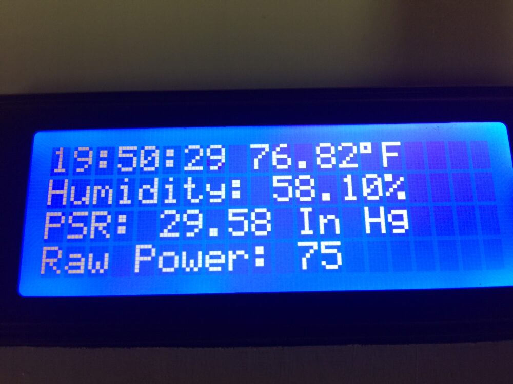
lcd.setCursor(0,1);
lcd.print(“Humidity: “);
lcd.print(humidity);
lcd.print(“% “);
lcd.setCursor(0,2);
lcd.print(“PSR: “);
lcd.print(BMPpascal/3386.38867);
lcd.print(” In Hg “);
lcd.setCursor(0,3);
lcd.print(“Raw Power: “);
lcd.print(PowerLevelScaled);
lcd.print(” “);
}
ButtonTimeout = 0;
ButtonMillisStart = CurrentMillis;
if (BuzzerShutoffOK == 1) {
digitalWrite(BuzzerPin,LOW);
}
digitalWrite(LedPin,LOW);
analogWrite(FiringPin, 0);
ButtonFalling = 1;
}
// Alarm Logic
byte second, minute, hour, dayOfWeek, dayOfMonth, month, year;
readDS3231time(&second, &minute, &hour, &dayOfWeek, &dayOfMonth, &month,
&year);
if ((hour==5) and (minute==0)){
//Serial.println(“Alarm”);
BuzzerShutoffOK=0;
digitalWrite(BuzzerPin,HIGH);
}else{
BuzzerShutoffOK=1;
}
if (!UpPowerValue and !DownPowerValue and !PowerBoostState){
analogWrite(FiringPin, 0);
lcd.clear();
lcd.setCursor(0,0);
lcd.print(“Opening Garage Door”);
lcd.setCursor(0,1);
lcd.setCursor(0,1);
lcd.print(“Connecting Door… “);
Serial.println(“AT+CIPSTART=\”TCP\”,\”192.168.1.178\”,80″);
delay(2000);
lcd.setCursor(0,1);
lcd.print(“Setting Length… “);
Serial.println(“AT+CIPSEND=20”);
delay(1000);
lcd.setCursor(0,1);
lcd.print(“Sending Command… “);
Serial.println(“GET /?DoorCMD=DC”);
Serial.println(“”);
delay(3000);
lcd.setCursor(0,1);
lcd.print(“Closing Connection “);
Serial.println(“AT+CIPCLOSE”);
delay(1000);
lcd.clear();
}
}
//—————————————-
Upload your project:
Remove the nano from your project, and connect it to your PC. Verify the code above, and install any libraries with you are missing.
Locate this line in your code: //setDS3231time(30,16,18,7,1,9,2017); Remove the “//” and set the clock a minute fast. This string is i the format: seconds, minutes, hours, day, date, month, year.
10 seconds before the set time is reached, press the upload button in your arduino IDE. Verify that “upload complete” is displayed roughly when the set time is at the actual time of day. Now, comment out this same line using “//” before the setDS3231 time function, and upload again. This will ensure the time is not reset every time you power the arduino.
Testing your project
Check for any shorts with your multimeter. Check continuity of all connections to ensure you have no broken wires.
Turn the voltage regulator down to zero.
Be sure to insert the batteries correctly. You can test this with just two batteries in series with each other on either side.
Using a voltmeter turn the buck converter up until you have 5volts.
With no atomizer attached, ensure that all of your circuitry is working properly. The back of the LCD display has a contrast display that you will need to adjust. Hold the firing button in for at least 6 seconds. The buzzer should sound.
Go outside the house to an open area, and place your atomizer into the 510 connector. Take care to have the ability to remove it quickly if it starts to fire immediately.
Again… Be ready to remove the atomizer or batteries immediately in case something goes wrong, and test fire the atomizer. The default power is around 20%. You may need to increase or decrease the power level using your power buttons, or power boost button. The display will read RAW POWER on a scale of 0 to 255…. 255 being 100%.
If everything works well, you are in good shape! Be sure to always remove the batteries when unattended. By default, the alarm will sound at 5am each morning. To change this, just adjust this line of code:
if ((hour==5) and (minute==0)){
Again — You assume all liability if you try to implement this. I’m just documenting the project here for my own reference.
Hints for your garage door opener: You can use another ESP8266 in your garage using EasyESP firmware. An output on the ESP8266 can be connected to a transistor controlled relay, which simulates pressing the pushbutton. You will need to adjust the IP address in the vape code, and the command you are sending to activate the relay. Some additional code might be required to to shut off the relay one second later.
In my case, I just had an arduino uno board with an Ethernet shield, and programmed it as a web server to turn on the relay for once second when it receives the proper GET command.
Review of important warnings:
- The delay() function could prevent your MOSFETS from shutting off while the power level is higher than 0. That is why this code uses a snapshot of the currentmillis to keep track of timed features. This way the loop can continue to scan, and shut off the MOSFETS at a reasonable time.
- High temperatures can damage your batteries. I personally will not use the vape feature if the temperature is reading over 95F.
- Again, be extremely careful to place your batteries correctly, and that they all have the same charge and capacity. Failure to ensure this could lead to an explosion.
- Ensure the 15K resistor has good contact between the source and the gate. Failure of this resistor could cause a permanent “ON” Condition of the MOSFETS
- The – Potential (ground) must be the same for the controller (arduino), and the MOSFETS. If the potential is not the same, the MOSFETS could fire at will!
- MOSFETS can short. Be prepared to remove the batteries at any time. It might be a good idea to add a high current safety switch to disconnect the atomizer from the main power source if needed.
- Be aware of the hazards of the vape itself.
- If the vape “Steam” is getting inside your box, you might want to add a small fan to pressurize your box slightly, or apply a seal where the box closes.
- There is no low voltage cutoff feature at this implementation. Do not allow any cell to discharge below 3.2 volts (2.7volts at very minimum) The voltmeter will typically read 6.4 when I re-charge the batteries.
- Use Ohm’s law. Check the battery’s current rating against the resistance of the coil to ensure you are not pulling too many amps. Periodically check the batteries and MOSFETS to ensure they are not getting too hot. MOSFETS can get too hot to touch, so be careful.
- Check all connections. A loose connection could cause heat to build up at the junction.
- Be aware of laws in your locality on building your own personal device.
— Ricky Bryce
Pingback: Arduino Bottom Feed Vape Mod -- built with Arduino Nano.