
Alinco DM1350 Power Supply Failure
I wanted to share my experience with you about a power supply failure, and how I found the problem. My Alinco DM1350 is an older power supply, which was hit with lightning. After the lightning strike, the power supply was no longer functional.
After opening the cover, I found that the Operation Amplifier (Op-Amp) was blown apart.
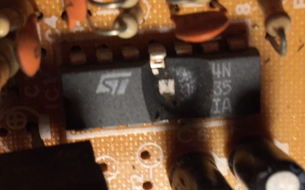
I replaced the 324 Op-Amp chip, but this time I used a socket, so it’s easier to replace next time. When I powered the unit back up, however, the maximum output of the supply was only half a volt!
Looking at the Schematic
It’s time to look at the schematic for this board to see what is going on. The Schematics are from Alinco, who is the manufacturer of this power supply.
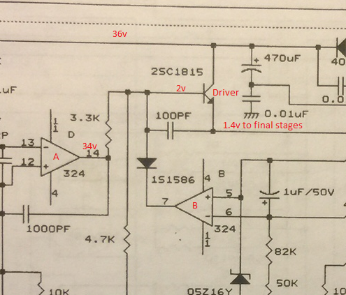
The Triangles (A & B) are part of the Op-Amp chip that I replaced. There are 4 internal Op-Amps on this chip, and here we see two of them. There is some gain on the operational amplifiers. For the purpose of providing a simple explanation, we will assume the gain is infinite. If the voltage on the + terminal is higher than the voltage on the – terminal of the Op-Amp, the output will be high. If the voltage at the – terminal of the opamp is higher than the voltage of the -, we will assume the output is “Ground”.
Look at the Op-Amp that I’ve labeled A. It seems to do it’s job. It’s providing 34v out (from pin 14) in an attempt to drive the base of the transistor. The problem is the base of the transistor is only receiving 2 volts when I measure it. This means that something is sinking the current to ground very badly! The only thing that can do this is a controlled way is Op-Amp B. Let’s take a closer look at Op-Amp B.
Finding the ground
Let’s look at the schematic again to find out why we are getting a path to ground on Op-Amp “B”.
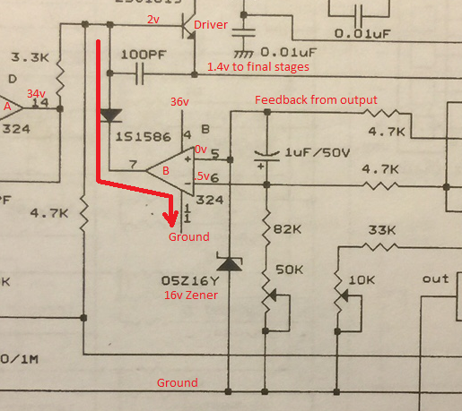
We know how an op-amp works now. Looking at Op-Amp “B”, if terminal 5 is at a higher potential than terminal 6, the output will be a + voltage. If terminal 6 is at a higher potential, then terminal 7 will be at (or near) Ground potential. In this case, we know that terminal 7 is at ground because of the voltage drop across the 3.3k resistor near Op-Amp A. We also know that terminal 7 will only be at ground if terminal 6 is at a higher voltage than terminal 5 (which it is).
The question then becomes, “Why is terminal 5 grounded”. The only way terminal 5 can be grounded is the the 16v zener shown in the schematic. The Zener diode, should not start to conduct, however, until terminal 5 is at 16 volts. The problem is the 16V zener is ALWAYS conducting.
Because the 16v Zener is always conducting, terminal 5 is always at zero volts. This means that the inverting input (terminal 6) to the Op-Amp is always higher than the non inverting input (terminal 5). Therefore, terminal 7 is always at ground, Because terminal 7 is always at ground, any power to the base of the driver transistor is diverted to ground.
By replacing the 16v Zener, the power supply is now up and running, and I’m getting a full 12v output!
— Ricky Bryce