
Introduction to the PLC-5 Enhanced Processor
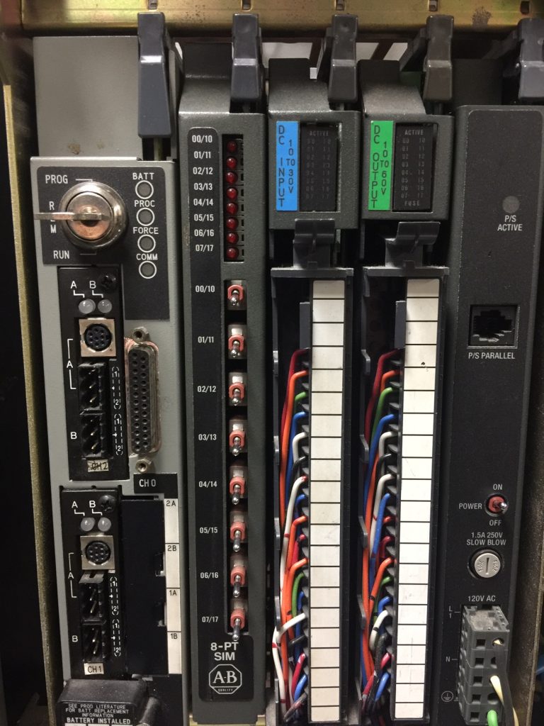
The PLC-5 Enhanced processor controls automation equipment. Program and troubleshoot the processor using RSLogix 5 software. You can also use older software which is DOS based, such as 6200, AI, or Taylor software. Basically, the processor reads data from inputs such as switches. This will gather the status of your equipment. Next, the processor runs logic which will determine what actions need to be performed. Finally, the processor writes to the output modules to control devices such as solenoids, and relay coils. The PLC-5 enhanced processor is shown on the left.
The Battery
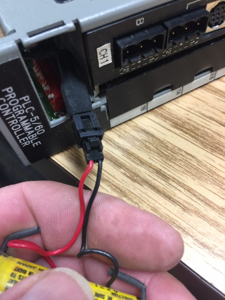
A 1770-XYC battery is a lithium battery that backs up the memory of the processor. Without a battery, you need to download the processor program every time power is cycled. Allen-Bradley states this battery will last up to 2.5 years, however, from experience, this is a conservative number. I’ve seen the battery last as long as 7 years if the chassis is always powered. When the battery is low, a battery light will energize on the processor. Be sure to change the battery with power on the processor (if possible) to avoid loosing the project. Also, be sure to dispose of the old battery properly.
To replace the battery, remove the battery compartment door. If the new battery is good, the battery light should immediately shut off when you replace the battery.
Communication Channels
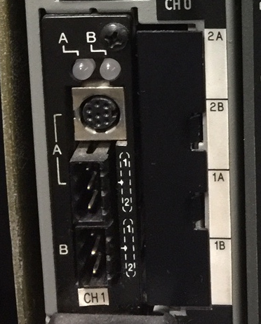
Channel 1 and 2
The communication channels allow the processor to interface with remote chassis, an HMI, or Programming/Troubleshooting terminal. First, let’s look at Channel 1. Channel 1 has two “sub” Channels: 1A, and 1B.
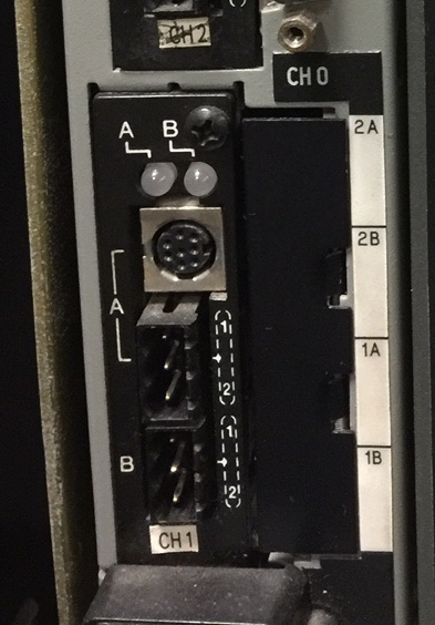
Channel 1B defaults to “Remote I/O Scanner”. We use this to interface with other devices that act as a remote I/O Adapter such as the 1771-ASB, Drives, Block I/O, etc. Using Belden 9463 cable, the remote I/O network can be as long as 10,000 feet running at 57.6 kbps. When running a remote I/O network at 57.6kbs, terminate both ends of the network with a 150 Ohm half watt (non-inductive) resistor. Other baud rates include 115.2kbps, or 230.4 kbps. Faster speeds are more limiting on the network distance, and could change the value of the terminating resistors that you use.
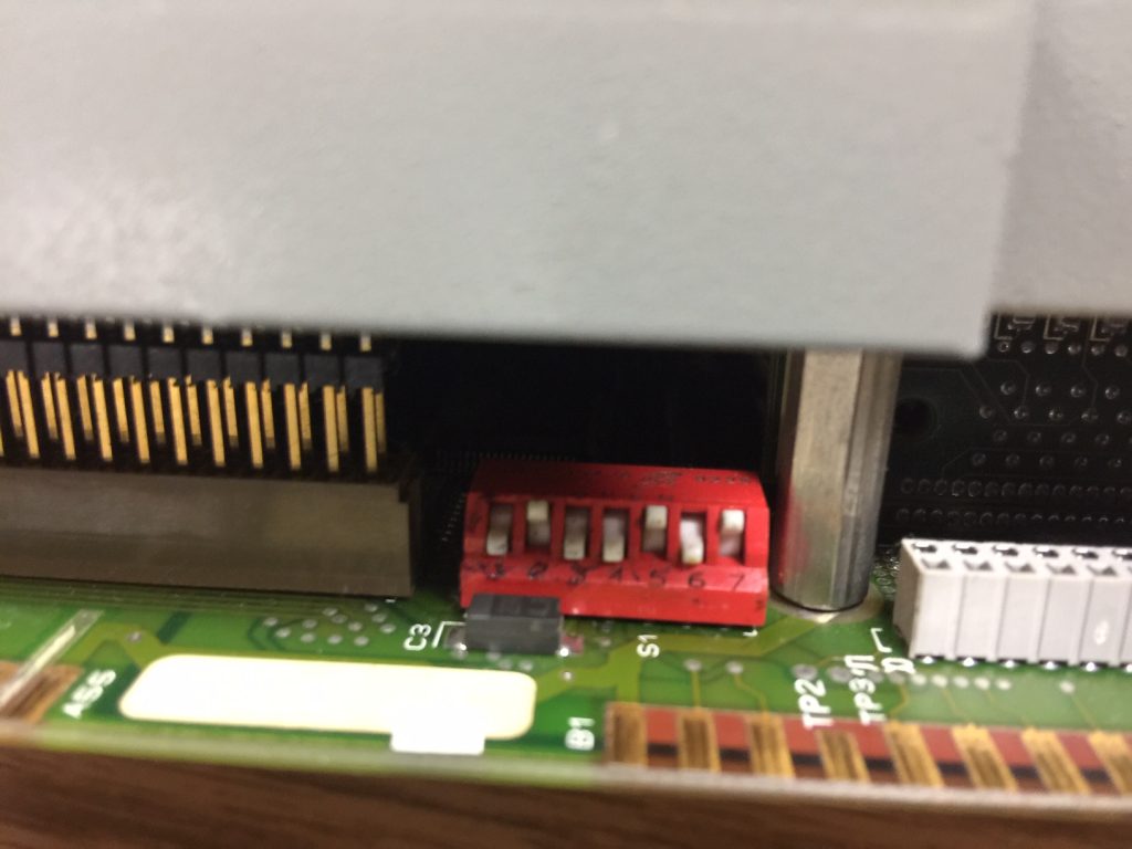
Channel 1A defaults to DH+. A DH+ Network is for peer to peer communication. Processors communicate with each other over the DH+ Network. Other devices, such as an HMI, or programming terminal might also reside on the DH+ Network. As with Remote I/O, use belden 9463 (blue hose) cable to connect devices together over DH+. Each device on the DH+ Network has a node number. To set the node number of channel 1A, use the dip switches on the side of the processor. The label on the processor will guide you on how to set the station number. Valid DH+ Station numbers are 0 to 77 (octal).
Likewise, Channel 2B and channel 2A are programmable. This will give you extra ports for other DH+ or Remote I/O networks if needed.
Channel 0
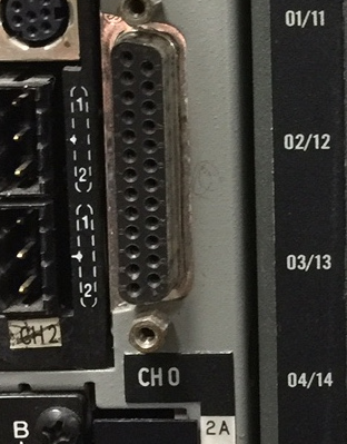
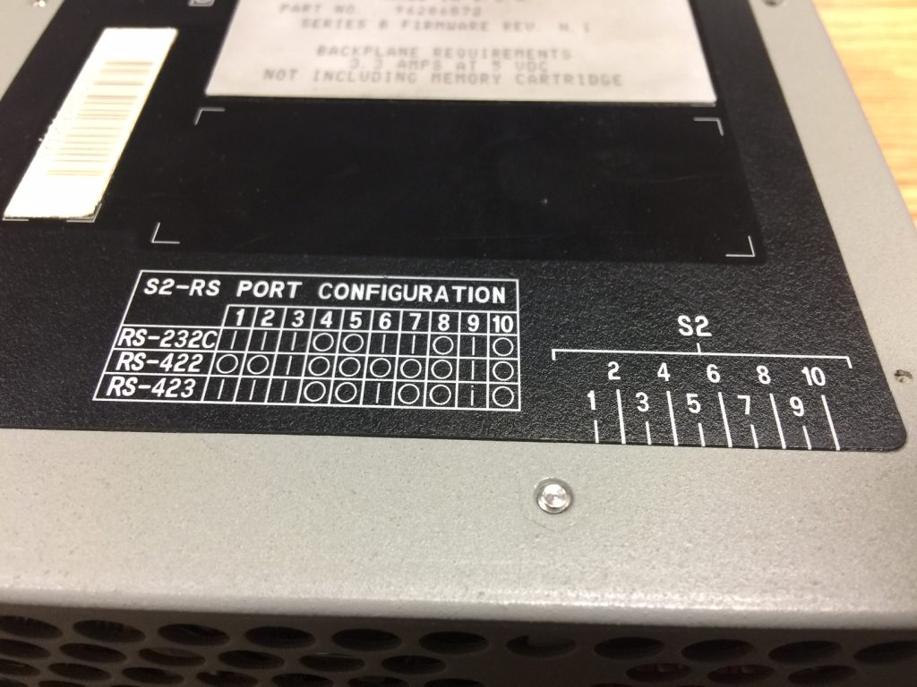
Set channel 0 to RS232, RS422, or RS423 by DIP switches on the bottom of the processor. Typically, you will set channel 0 to RS232 mode, and use a NULL modem cable to connect channel 0 of the processor to your PC. The cable from Allen-Bradley for this is a 1784-CP10.
Key Switch
The key switch has 3 positions: Run, REM, and Prog. Unquestionably, the most common position is REM. This position allows you to do almost anything you need to do from the PC. However, when the key is in RUN position, you cannot download to the processor. Likewise, you cannot perform an online edit. This key position is used to ensure certain security precautions. When the key is in PROG, the logic does not execute.
Status Indicators
The status indicators are a very useful tool for troubleshooting the processor and communication.
Channel 1 and 2 (A and B)
Solid Green (all channels) — The channel is communicating properly, and no action is required.
Flashing Green — For a DH+ channel, this indicates that no other nodes are on the network. However, if the channel is configured for Remote I/O, at least one (but not all) devices are not communicating properly.
Flashing Red — For a DH+ Channel, this indicates that a duplicate node number has been detected…. Verify your witch settings. Likewise, if the channel is configured for Remote I/O, no devices are communicating.
Solid Red — This indicates a hardware fault. Although cycling power could solve the problem, if this is a critical system, consider replacing the channel, or the processor.
General Status Indicators
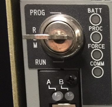
BATT: When the battery indicator is on, change the battery within 10 days. It’s important to realize that you might not know how long the battery light has been energized. It’s best to change the battery as soon as possible. Change the battery with the processor powered up if possible. Otherwise, you will loose the program in the processor’s memory.
PROC: If solid green, the processor is running the program. However, if the PROC light is solid red, the processor could have lost the program. Likewise, a solid red PROC light could indicate a bad EEPROM, bad switch configuration, or a bad processor. If PROC is flashing red, this indicates a major fault. Go online with the processor to see what the fault condition is. A Flashing green PROC light indicates that you are transferring memory to EEPROM.
FORCE: Forces simulate real world jumpers in the program (to some degree). If the force light is flashing amber, this indicates that forces are installed, but not enabled. Conversely, a solid amber force light indicates that installed forces are enabled in the processor.
COMM: The COMM light will flash (or flicker) green as the processor passes information across channel 0.
For a complete list of all the status indicators on any processor, visit the PLC-5 Quick Reference Guide. Chapter 5 of this guide is the troubleshooting section.
For more information on the PLC-5 system, visit the PLC-5 Category Page!
— Ricky Bryce