
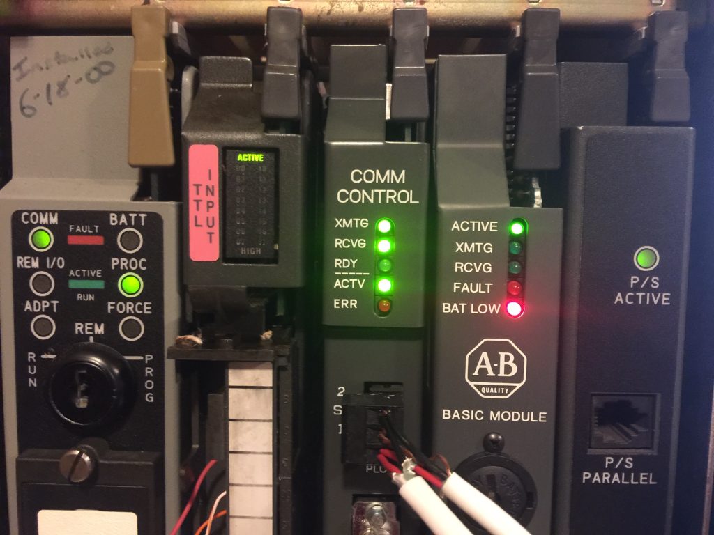
Introduction to the 1785-KE Module
The 1785-KE module allows you to easily interface with a Data Highway Plus (DH+) Network. Although there are other ways to interface with DH+, I have found this method to be the most cost effective. For example: The 1784-U2DHP module could cost over $2000. You can usually find a 1785-KE module from Ebay for under $100. Other methods include a ControlLogix gateway (with an Ethernet and a DHRIO module), or an ANC-120e.
Configuring the module
The configuration is very simple. Although there are a lot of switches for configuration, the KE module has a label to describe each switch.
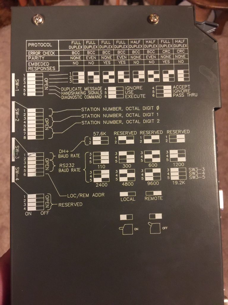
This looks intimidating, but I set all of the switches in the DOWN position except for the very first switch, and the switches for the station number. This provides for a common serial setting of 19,200 baud, 8 bit word length, 1 stop bit, Full Duplex, and CRC error checking.
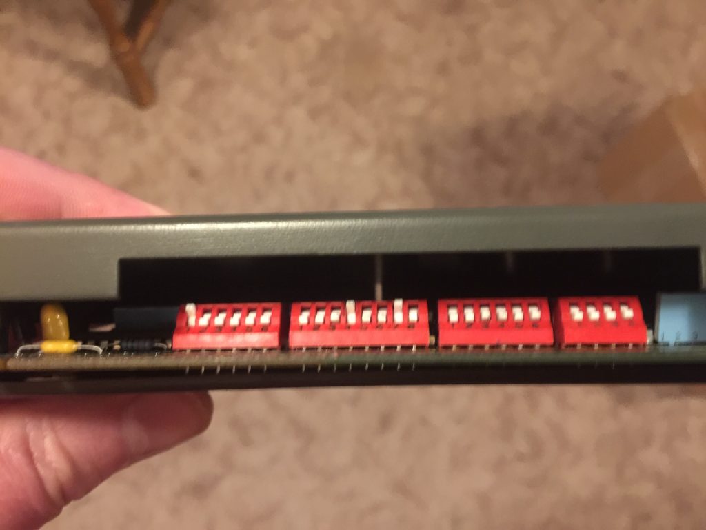
As can be seen in the above image, I put the very first switch in the up (off) position. The second bank is for the DH+ Node address. By all means, do not use a node address that already exists on the DH+ Network. The node address is in octal. The first two switches represent the first digit of the octal node (in binary). Because these switches are down, the first digit is 0. The next three switches represent the second digit of the octal node. In this case, (010) in binary is 2. The last 3 switches represent the last digit of the octal node. Likewise, this digit is also 2. Summing up, our node is 22. With these settings, the DH+ Baud rate is 57.6k (which is the only baud rate this module supports for the DH+ Port.)
Wiring the the module
The most difficult part of getting the module up and running is setting up your serial cable. As can be seen, I just used breakout terminals. You need a 15 pin (2 row) male connector, and a 9 pin female connector.
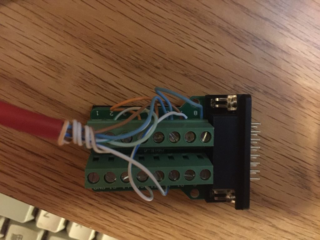
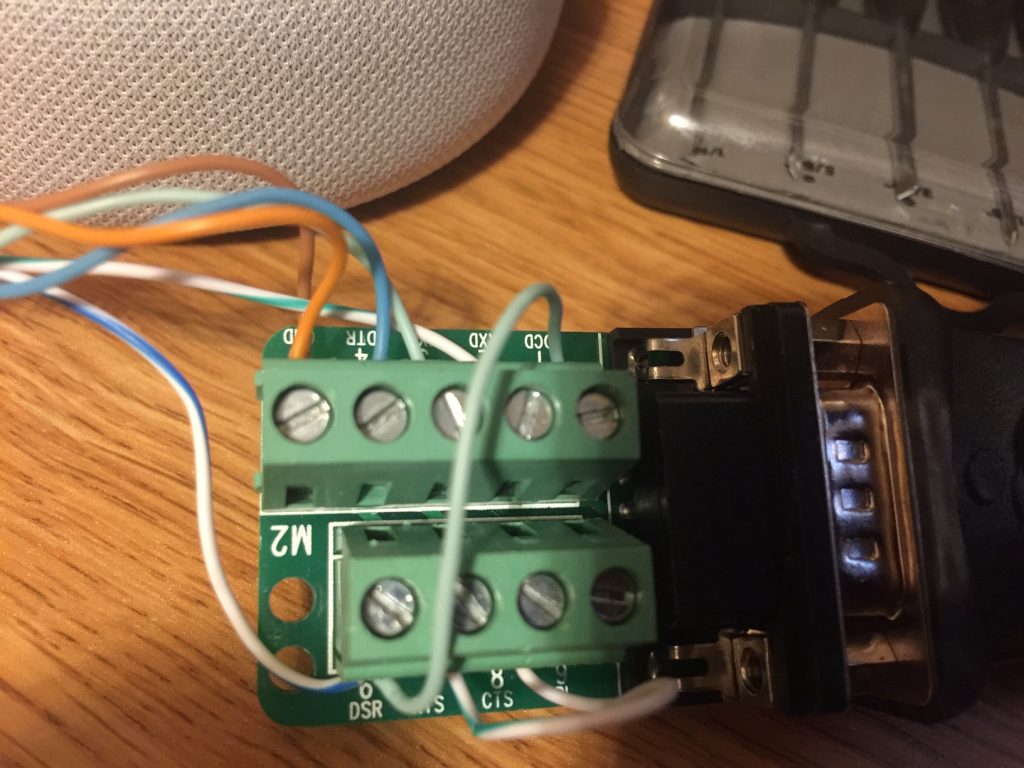
It’s difficult to see in the image, so I will list the connections below. I had to research a little, because the manual for the 1785-KE module shows the connection to a 25 pin connector. I cross referenced each pin to a 9 pin connector to use on more modern computers or USB to serial adapters.
Jumpers on the 15 pin connector: Jump pins 7 to 15 (GND to GND). DSR (6) to DCD (8). RTS (4) to CTS (5)
Jumpers on the 9 pin connector: DCD (1) to DSR (6). RTS (7) to CTS (8).
Connections FROM 15 pin TO 9 pin connector.
TXD (2) to RXD (3)
RXD (3) to TXD (2)
DSR (6) to DTR (4)
DTR (11) to DSR (6)
GND (7) to GND (5)
For the DH+ Plug, connect your DH+ Network to the 3 pin phoenix connector. Clear is usually #1 terminal on DH+, Shield in the center, and Blue on #2. Check the rest of your nodes on the DH+ network to be sure the same color conductor is wired to terminal #1 and #2.
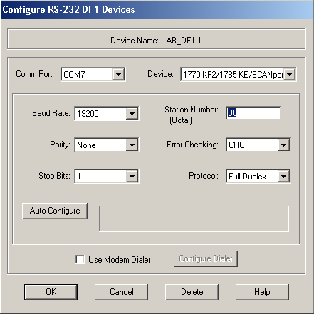
Configuring the driver in RSLinx
RSLinx is the communication server. When configuring RSLinx, use the DF1 RS232 devices driver. Be sure to select the proper COM port. The Device will be the 1785-KE as shown. I like to set the station # on 0. If you use the Autoconfig button, your workstation will be set to the node number of your KE on DH+. In essence, the workstation shows up in RSWho instead of the KE module if you use this setting.
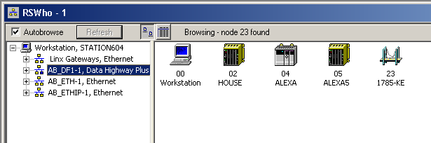
When you look at the RSWho screen, you should see the rest of the network: As can be seen, I have a different 1756-KE module currently running on Node 23 octal, and I’ve set the workstation (within the driver configuration) to Node 0.
For more information on the PLC-5 system, visit the PLC-5 Category page!
— Ricky Bryce