
Introduction to PLC-5 Block Transfers
One of the most difficult concepts for most people to grasp is the PLC-5 Block Transfers. Think of Block Transfers as simply a copy instruction. You are copying data from a module to somewhere else in the memory of the processor. The Block Transfer Read (BTR) will read up to 64 words from a module. Likewise, the BTW will write up to 64 words to a module.
Why Block Transfers are needed
The reason we use block transfers is because of the I/O Structure of the PLC-5. In 1-slot addressing, only 1 group is available to each slot. A group is 1 word (16 bits) of Input, and one word of Output. Because some modules have many words, a block transfer is required to retrieve the data from the module. Examples of modules that need block transfers are the analog input modules, analog output modules, Devicenet scanners, and the BASIC module.
Think about a 16 channel Analog Input module. This module has 16 analog input channels. Each channel requires 1 word of memory. Furthermore, the module has 4 words of status. We need to read 20 words from the module, however, only 1 word of input is available in the I/O table.
Consider the following chassis:
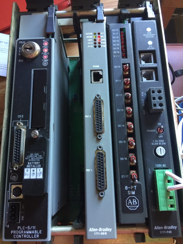
This is a 4 slot chassis in 1 slot addressing. Notice that group 0 is empty. Secondly, we have a BASIC module in group 1. Additionally, group 2 is a simulator module. Finally, group 3 has a power supply.
In this post, we’ll use RSLogix to automatically set up the block transfers to the Basic Module. We will read 64 words from the module, and write 64 words to the module.
Set up the I/O Configuration
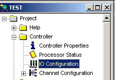
Surprisingly, RSLogix 5 has the ability to write the block transfers for us. First, go to I/O Configuration.
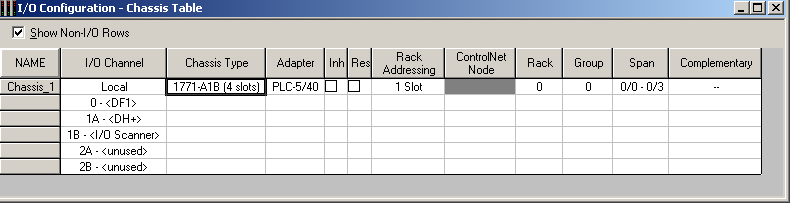
Next, I’ll double-click the 4 slot chassis. You may need to change the chassis type to another size for your application, or even add chassis to remote I/O. In this post, I’m going to keep things very simple.
I’m going to document the modules in the 4 slot chassis.
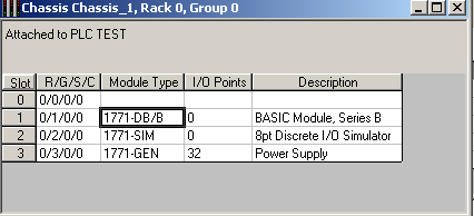
Given that we have a basic module (1771-DB) in group 1, I’m going to double-click the module to enter it’s configuration.
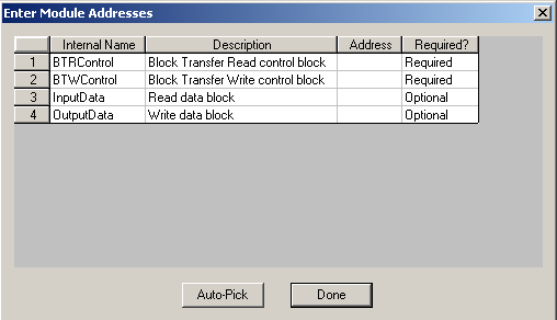
Important to realize that if you already had a running program, and the block transfers were previously set up, do not Auto Pick. You will need to find the block transfers in your logic, and enter the addresses manually. However, because this is the first time setting up the module, I don’t care what addresses we use. I will Auto Pick. As can be seen, the next available free data files are picked by RSLogix.
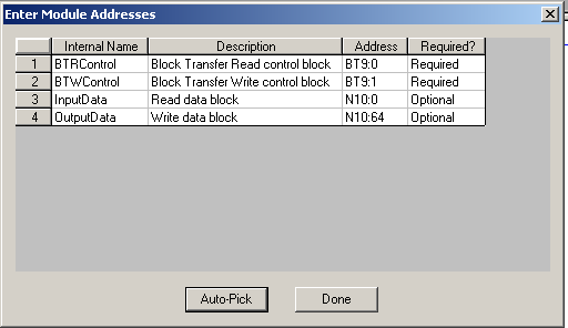
Now click “Done”.
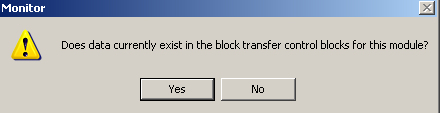
Since this is a new module setup, data does not already exist for the module. On the next screen, I will choose “No”.
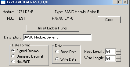
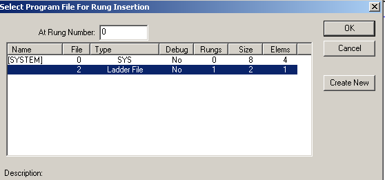
At last, we will insert the rungs. Be sure that all other fields are set up properly for your module before clicking the button to “Insert Ladder Rungs”.
I will place this logic in Ladder 2 starting on Rung 0.
Review the Logic
Look at the block transfers to ensure they make sense.
In this case, the block transfer write instruction will take 64 words of data from the N10 Data file starting at word 64. These 64 words will be sent to Rack 0 (Local chassis) Group 1 (Basic Module) slot 0. Because we are in 1 slot addressing, the slot is 0. If you use 2 slot addressing, each group will have a low (0) slot, and a high (1) slot. The data from N10:64 to N10:127 will be written to the module. Likewise, the data we read from the module will appear in N10:0 to N10:63. The control block (BT9) is simply a workspace for the block transfer to operate. This will store the configuration and status of the block transfer itself.
As always, this post is simple a sample post. You must adapt the information contained in the post to fit your own needs. Always be aware of any safety considerations, and consult the manuals for your module.
For more information on the PLC-5, visit the PLC-5 Category Page!
— Ricky Bryce