
Introduction to Troubleshooting with Add-On Instructions
Today, we’ll look at a method for troubleshooting with Add-On Instructions. Add-On instructions make life easier for both the programmer, and the troubleshooter. However, it’s important to understand how add-on instructions work, and why we need them.
In the older processors, the programmer wrote the same code over and over again for similar devices. Unless they used Indirect addressing, this made the project extremely large, and consumed a lot of resources. In other words, there was a lot of redundancy.
With Add-On instructions, the programmer writes one instruction to control all devices of the same type. Afterward, he can use this instruction many times in the main logic.
A Quick Look
Here, we have and add-on instruction for room lighting.
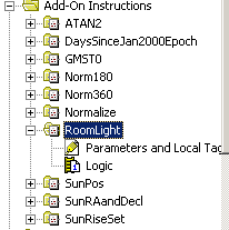
As can be seen, the add-on instruction consists mainly of two components: Parameters (Tags) and Logic. The Tsgs are the values passed into and returned from the instruction. By comparison, the logic manipulates these parameters to determine what values to return.
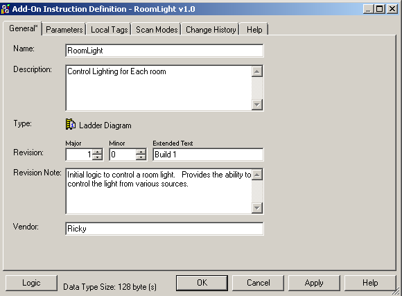
Right-click the add-on instruction to open it’s definition. The general tab shows basic information about the instruction.
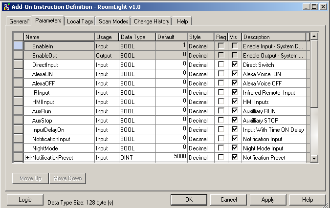
The Parameters are values we will pass into the instruction. For examples: Input parameters for a MUL instruction are Source A and Source B. The MUL instruction has one output parameter – The destination. Add on instructions, however, might have many input and output parameters. In this case, our input parameters are mostly switches, and the output parameters are for the devices we wish to control.
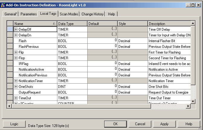
Local tags are internal tags for the instructional logic. This includes timers, counters, internal bits, etc.
In the bottom left corner, I will press the “Logic” Button. this will show the logic of the instruction how it is written.
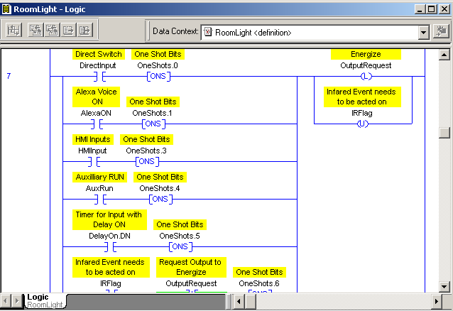
This particular instruction has 21 rungs of logic to read the values we send into the instruction, manipulate data, and determine when to provide outputs.
Using the Add-On Instruction
Creating the add-on instruction alone is not going to control any real device. We must now use our add-on instruction in the main logic! it’s important to realize that just because the add-on instruction is written in ladder logic does not mean we are limited to using the instruction in ladder routines. In this case, I will demonstrate how I will use this instruction in Function block routines.
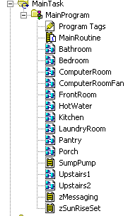
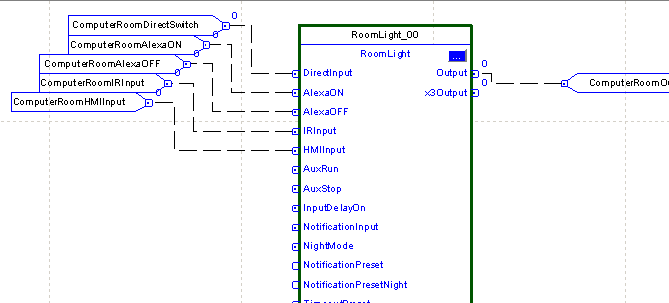
Since this instruction controls lights, and every room has a light, I will use the instruction in mot all of these routines. Let’s take a look at how the instruction appears in a function block diagram:
In this case, the instructions inputs appear on the left side, and the outputs appear on the right. If you want a similar appearance in ladder logic, you can set this up under Tools | Options as well. The parameters are shown inside of the instruction block. When I tie an Input Reference (IREF) into the parameter, the instruction will use the value of the tag for the parameter. For Example: The value of the Controller Tag “Computer Room Switch”, is passed to the Parameter “Direct Input”, and is used in the instruction’s logic. Likewise, the parameter “Output” within the instruction logic is passed to the controller tag “Computer Room Output”. Next we’ll discuss how to do Troubleshooting with Add-On Instructions:
View and navigate the Instruction Logic
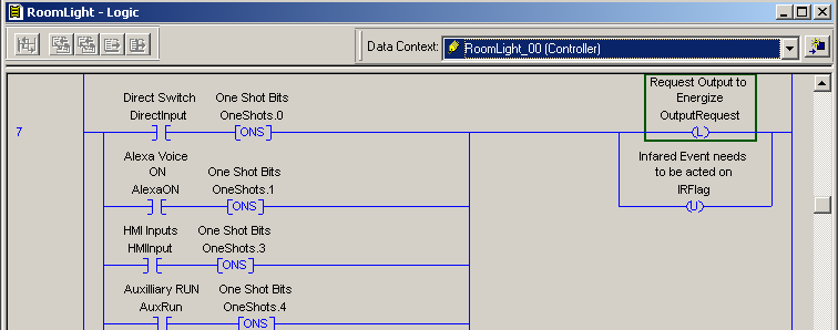
Next, we will view the instructions logic. To do this, Right-Click the instruction, and choose “Open Instruction Logic”
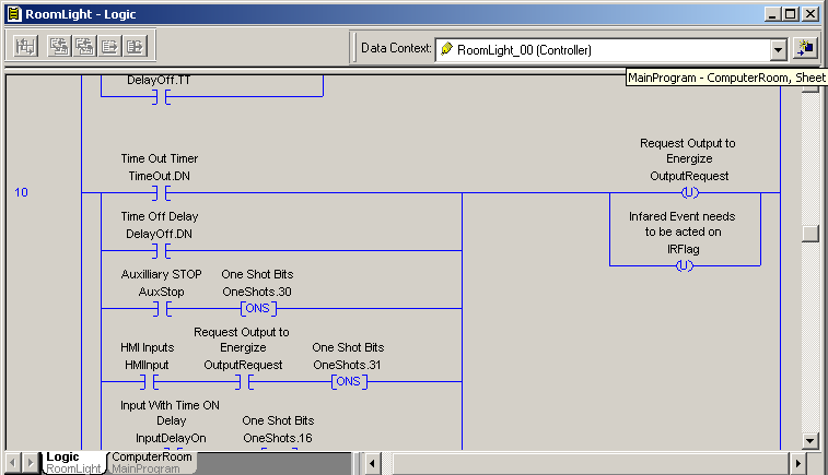
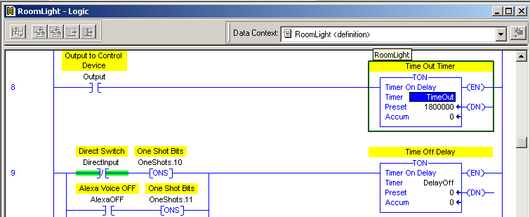
Pay close attention to the “Data Context”. As can be seen, the Context is RoomLight_00. This is the tag the logic is using to populate the true/false conditions. In truth, when you cross reference within the instruction, the context will be changed to the “Definition”, which is default values. All in all, by choosing the context, you are seeing what is happening with the ComputerRoomLight. RoomLight_00 is the “Workspace”, or the Tag that is on the instruction to control the ComputerRoom light.
In this case, let’s say we want to cross reference the Time Out Timer. I will Cross Reference the local tag “TimeOut.DN”.
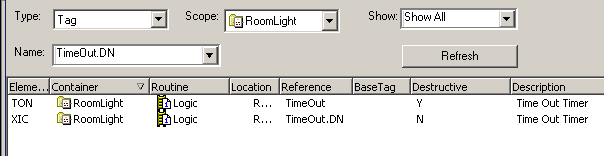
When you cross reference, you will usually go to the instruction that is Destructive. (with a Y in the destructive column). This is the instruction that has the ability to change the value of a tag. In this case, I will go to the TON instruction.
Check the Definition of the Add-On Instruction.
As I have said…. Notice the “Data Context” has changed back to the “Definition” This means the logic is no long being populated with values that control the ComputerRoomLight. Change the Context back to RomLight_00.
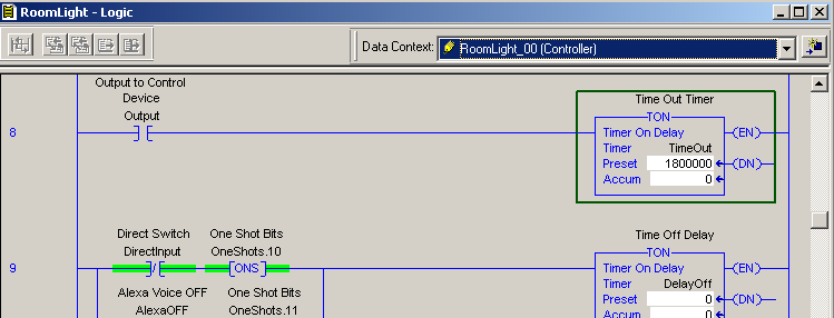
The current values of the ComputerRoomLight happen to be at default values, but if the output was on, at this point, you would see the accumulated value increasing.
Likewise, if we need to find out why the timer did not start, cross reference the Output tag, and go to it’s destructive instruction.
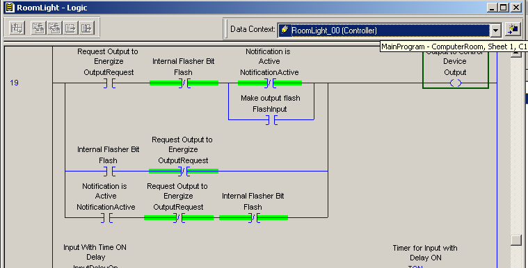
Next, we ask ourselves which branch to take…. Since I know I’m not in flash or notification mode, I will cross reference the OutputRequest. Go to the destructive instruction, which is an OTL in this case because we want to turn the light on. Once again, don’t forget to change the context back to ReomLight_00!
Transition back to Main Logic
Finally, we have come to the inputs that will request the light to come on. I will cross reference the tag “DirectInput”, and see what happens!
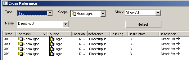
There is nothing destructive to go to! In reality, when we cross reference a tag or parameter within an instruction, and it does not have a destructive bit a troubleshooter would get a little confused at this point. This is why it’s important to realize the parameter usually comes from the face of the instruction.
Look at the face of the instruction. We know know what to trace down next. The parameter “DirectInput” comes from the tag “ComputerRoomDirectSwitch”. Therefore, this is the tag that you need to cross reference now, and trace it down in the main logic.
It’s important to realize that if you cross reference a tag within an instruction, and there is no destructive, and there is no parameter on the instruction’s face, other logic could be moving values directly into parts of the instruction’s context. If this is the case, you could have right-clicked RoomLight_00 to monitor the tag (either a controller, or program tag), then cross reference the tag’s element in the main logic to find it’s source of data.
Some people are a bit intimidated when troubleshooting with add-on instructions. On the contrary, with a little practice, they make a project much easier to read, and to manage.
To learn more about setting up your own add-on instructions, visit the Add-On Instruction Post!