
Introduction — ControlLogix Message to PLC-2 Processor
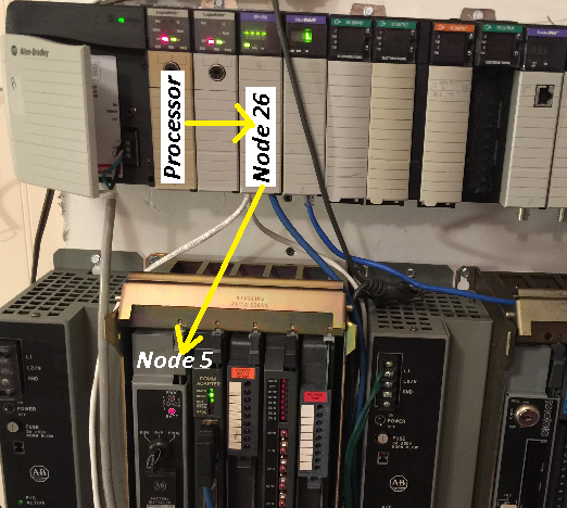
In this section, we’ll cover how to send a ControlLogix Message to the PLC-2. The PLC-2 is now old, and obsolete. However, there are still quite a few systems that exist, and we need to get data from them. In this case, we’ll send 3 words to a PLC-2. The PLC-2 is connected to the Data Highway Plus network through a 1785-KA3 module. The KA3 Module is set for Node 5. Likewise, the 1756-DHRIO module (Channel A) is at Node 26 on the DH+ Network.
Create the Tags
First, in the ControlLogix processor, we’ll create some tags that will allow our message instruction to operate. Under “Edit Tags”, create the following tags in the controller tag database:
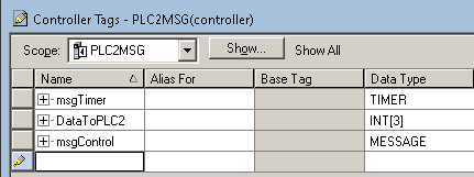
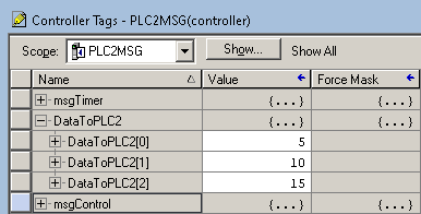
We’ll use the tag “msgTimer” to trigger the message instruction in logic. In contrast, we’ll use “msgControl” as the workspace of our message instruction. Lastly, the tag “DataToPLC2” will contain the data we wish to send to the PLC-2/17 processor at Node 5. Meanwhile, let’s go to “Monitor Tags”, and populate the tag with random values to see if they later arrive at the target processor. Just remember this is a PLC-2, so I’m not going to send over 3 words, and the values will not exceed 8 bits (255 decimal).
Add the logic for messaging your PLC-2
In Short, we’ll add the following logic to the MainRoutine. The timer will reset itself every 100ms, and trigger our message instruction.
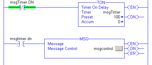
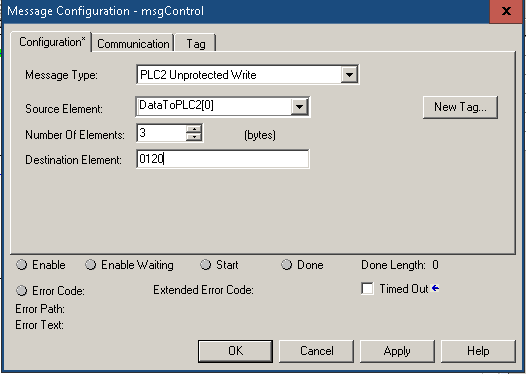
At last, we’ll configure the message instruction. Within the message block, click the “…” (grey button) to access the configuration screen. Notice our type is “PLC2 Unprotected Write”. The Source is “DataToPLC2[0]”, which is the first element we are getting data from. In the PLC2 processor, we’ll write to memory location “120”.
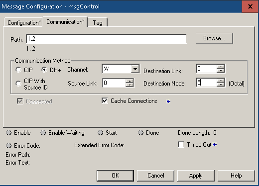
Next, we have to set the path, so go to the “Communication” Tab. In this case, the path is 1,2. The 1 gets us to the backplane from the processor. The next part of our path is “2”, for Slot 2. Once we are on the DHRIO module, we’ll pick up the communication method of DH+. Be sure to select the DH+ Radio button. Generally, we set Channel A to DH+. In brief, the mode of a channel and it’s node number are a hardware setting on the DHRIO module itself. The destination node is “5”. We set this by DIP switches on the KA3 module in the PLC-2 chassis. A 1771-CO cable connects the KA3 module to the programming port of the PLC2 processor.
Download and test your work
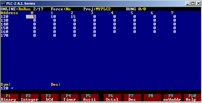
Finally we are ready for the real test. We’ll download to the ControlLogix processor. At last, we’ll check the Data Table in the PLC2 to verify it received the proper data from the ControlLogix processor.
For more information, visit the ControlLogix Category Page!
— Ricky Bryce