
Introduction to the ControlLogix Sequencer Output (SQO)
Basically, we use the ControlLogix Sequencer Output (SQO) instruction as a “Drum Switch”. That is to say, we have a file of bit patterns. Each time we trigger the sequencer output instruction, the next bit pattern will be dumped to the output. In this case, we’ll use an output module.
The ControlLogix Sequencer Output (SQO) Instruction has many uses. For example, we can blow different bags in a dust collector every few seconds. This way, we don’t deplete the air pressure by blowing all bags at once. Even some entire machine operations are set up using the SQO. A different bit pattern will be sent to the output module each time certain conditions are true. Of course a classic example most people think about is Christmas lights. Each time the sequencer advances, different outputs will energize.
This is an example only to illustrate how the SQO instruction works. By no means should you use this on your equipment without proper knowledge and taking the necessary safety precautions.
Set up the Logic
Before we begin, I’ll set up the following logic.
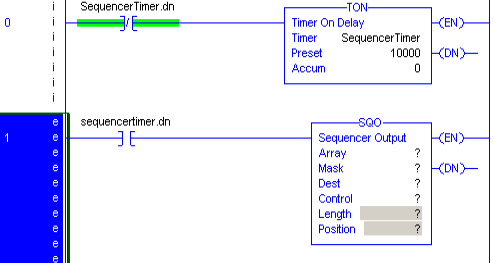
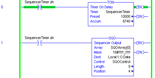
In this case, we have a timer that will trigger it’s own DN (Done) bit every 10 seconds. We’ll use this DN bit to trigger the SQO Instruction. First, let’s set up the array. I’ll type in SQOArray in the Array field. Next, right click this text, and assign this tag as DINT[10]. This gives us 10 different bit patters to send to the output module.
Now, set up the MASK. We usually specify the mask in Hexadecimal. Enter the bits you wish to use in Binary into you calculator (in binary mode). Convert this value to Hex. In this case, we’ll use all 32 bits. Therefore, the MASK is 16#FFFFFFFF. All 32 bits are in use. The 16# indicates that we are entering the mask in Hexadecimal (Base 16).
My destination is the output module. It’s address is Local:1:O.Data.
For the Control element, I just type SQO Control. Then, right-click the tag, and create a new tag. This tag will simply have the “Control” Data type.
The length is 9 elements. We use element 0 to initialize the output when we trigger a RESet instruction.
Configure the Array
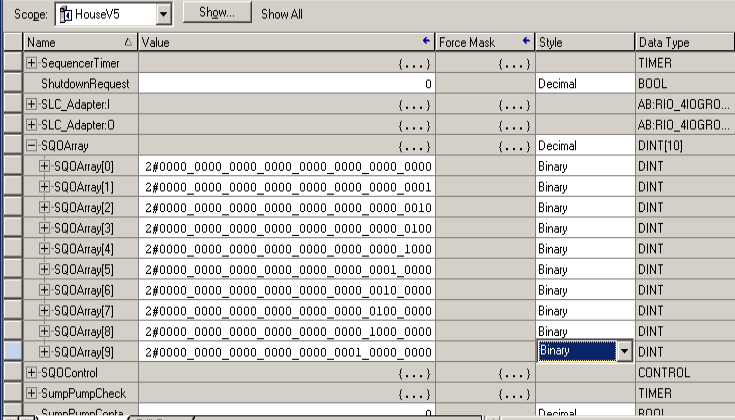
At last, we’ll go to tags, and turn on bits within SQO Array. Each element will represent a different bit pattern to send to the output module. For example, the initialization bit pattern is placed in SQOArray[0]. Obviously, the next bit pattern will be on SQOArray[1], and so forth. After the sequencer reaches position 10, it will start at position 1 again until you reset the control element.
Finalize your work, and your sequencer output instruction is running! Every 10 seconds, the next bit pattern is transferred to the output module.
For more information on CotnrolLogix, visit the category page!
— Ricky Bryce