
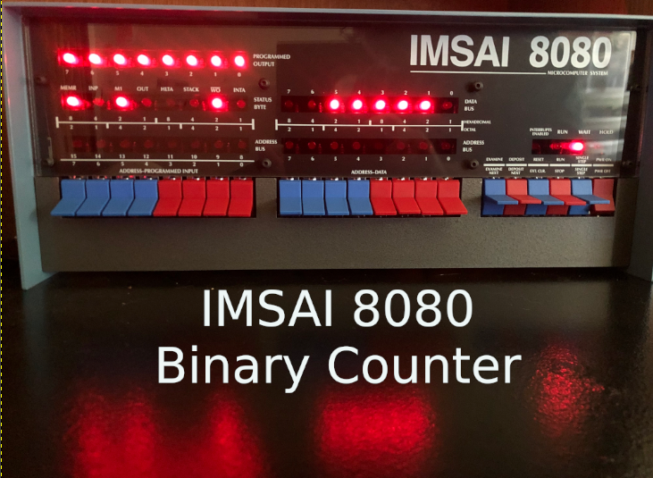
Introduction to the IMSAI 8080 Binary Counter
In this section, we’ll display the IMSAI 8080 Binary Counter onto the programmed outputs. Keep in mind the programmed outputs are in the upper left corner of the IMSAI front panel. Although there are several ways to do this, we’re going to concentrate on Assembly Language in this section. By programming in Assembly, you are learning exact instructions that your processor supports. In this case, that is the Z80. Once you compile this program, it will run on the 8080 processor as well since we aren’t using any special commands that the 8080 can’t handle. Remember that if you use an 8080 compiler though, the instruction set is much different.
About Binary
Basically, binary is how computers “think”. It’s a base 2 numbering system. On the other hand, our every day numbering system is base 10 that was use as humans. That is simply because we have 10 fingers. Think of the computer as having only 2 fingers. It only supports 0’s and 1’s at the processor level. Let’s take a look at a decimal-binary table:
Decimal   Binary
  00       0000
  01       0001
  02       0010
  03       0011
  04       0100
  05       0101
  06       0110
  07       0111
Each bit position represents a power of 2. We number the bit positions from RIGHT to LEFT, starting with 0. The right-most bit is the least significant bit (LSB). To convert a bit position to decimal, we simply take the bits that are high to the power of the bit position. Let’s try the number 6. This would be 2^1 + 2^2 = 6. (^ indicates “to the power of”). Now try 7. This would be 2^2 + 2^1 + 2^0 = 7.
Because the Z80 is an 8-bit processor, our maximum value for one byte is 255 (decimal). For this reason, our program will simply count up to 255 then stop.
Writing the Program
In this case, I’ll be doing everything on the IMSAI itself… Even the assembler. You can find Z80ASM at this link. Additionally, I’m using WordStar to develop the program as a non-document file. A non-document file is just a text file with no formatting. Check out this link for more information about using WordStar as an editor if you are not familiar with that.
I’m going to run WordStar, and Create a non-document file called BINARY.Z80. I’m going to save this to my B: drive.
At this point, lets take a look at the program:
   ORG 0100H        ; CPM PROGRAMS ORIGINATE AT 0100H
   LD A,0           ; INITIALIZE ACCUMULATOR
   LD B,0           ; INITIALIZE REGISTER B
LOOP:               ; LOOP LABEL
   LD D,255         ; SET REGISTER D TO 255
DELAY1:             ; DELAY 1 LABEL
   LD C,255         ; SET REGISTER C TO 255
DELAY2:             ; DELAY 2 LABEL
   DEC C            ; DECREMENT REGISTER C
   JP NZ,DELAY2     ; IF C IS NOT ZERO JUMP TO DELAY2 LABEL
   DEC D            ; ONCE C=0, DECREMENT REGISTER D
   JP NZ,DELAY1     ; IF D IS NOT ZERO, JUMP TO DELAY1 LABEL
   CPL              ; COMPLIMENT ACCUMULATOR (FLIP ALL BITS)
   OUT 255,A        ; SEND THE ACCUMULATOR TO THE LEDS
   INC B            ; INCREMENT THE B REGISTER
   LD A,B           ; LOAD REGISTER B INTO REGISTER A
   JP NZ,LOOP       ; AS LONG AS A IS NOT ZERO (ROLLOVER) GO BACK TO LOOP LABEL
   CALL 0           ; RESET SYSTEM
   END              ; END OF CODE
Spend some time looking at that program, and the comments I’ve added. You will see exactly what is happening. Basically, register B is our counter. so we start this off at 0. Additionally, register A also starts at zero. After running through our nested delay loops, we flip all the bits in register A, and send this to our display. The reason we flip all of the bits in register A is that our LED’s are backwards. In other words, if a bit is 0, the light is ON, and if a bit is 1, the light is OFF. We are just reversing this behavior by complimenting A before sending it to the LEDs
After that, we increment register B, then load this back to register A.
Once again after going through the delay loops, we compliment register A, and send that to our outputs.
In WordStar, I’m going to hit CTRL-K then CTRL-X to save and exit.
Assembling Your IMSAI 8080 Binary Counter
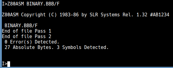
Now that we have save BINARY.Z80 on our B: disk, we are ready to assemble the program with Z80ASM. Simply type Z80ASM BINARY.BBB/F In this case, the assembler already assumes the filename has the .Z80 extension. Notice the .BBB. The first letter represents the drive that the source file is on. Secondly, the next B represents the target drive for our .COM file. Thirdly, the last B is the drive we wish to store the list file on, which is helpful in troubleshooting. The /F flag indicates to the assembler that we want a full listing in the list file.
Press enter, and you should have zero errors!
At last, we’ll go to the B drive, and run our program that we created called “BINARY”. Your programmed outputs will count up to 255, then reset back into CP/M.
For more information, visit the IMSAI Category Page!
— Ricky Bryce