
Introduction to ATTiny85 Programming with “Arduino as ISP”
This document will walk you though ATTiny85 Programming with “Arduino as ISP” using the Arduino (or compatible) as an ISP. We will make our connections, then program the Atmega328 (Uno board) to act as an ISP (In System Programmer). This example will use an Arduino Uno compatible board, but you can also use the Mega, Mini, Nano, or other boards to program your MCU (Micro Controller Unit).
Step 1 — Make your connections
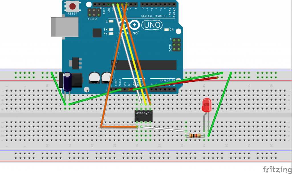
The connections are very simple. We just connect pin 10 on the Uno board to Physical pin 1 on our ATTiny MCU. Then pins 11, 12, and 13 on the Uno board will connect to physical pins 5, 6, and 7 on our ATTiny (respectively). We have a 10 microfarad capacitor between Reset and ground on the UNO board. Also, to prove our circuit works, we will use an LED connected to physical pin 2 (I/O pin 3) through a 1K ohm resistor. (See the diagram above)
Step 2 — Upload the Arduino Sketch
Now, let’s open the Arduino IDE. Be sure the board is set up for Uno (for this example), and set the port. Next, be sure to open the Arduino ISP Sketch. In version 1.8 of the IDE, this is example #11.
Temporarily remove the capacitor, and upload your sketch.
Replace the capacitor between Ground and Reset on the UNO. Be sure you have the polarity correct for this capacitor!!
Step 3 — Open your example sketch
Open the blink sketch example, and change the pin that we are writing to. This will default to Pin 13, or “BUILTIN”. Be sure to change both your setup function, and the loop function to reflect I/O Pin #3.
Step 4 — Set up your board as ATTiny85
If you have not already installed the ATTiny board in your Arduino, IDE, we will have to go to File | Preferences, and add this URL:
https://raw.githubusercontent.com/damellis/attiny/ide-1.6.x-boards-manager/package_damellis_attiny_index.json
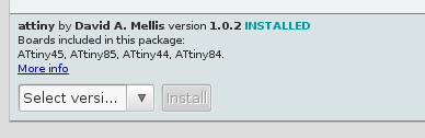
Next, Go to Tools | Boards, and go to the Board Manager. Scroll to the bottom, and install the ATTiny Processor.
Now go to Tools | Board, and Choose ATTiny 24/45/85
Go to Tools | Processor, and choose ATTiny85
Go to Tools | Port and select the port that your Arduino is connected to.
Step 5 — Upload your sketch
First, we must set the programmer to “Arduino as ISP”. We can do this by going to Tools | Programmer, and select “Arduino as ISP”
Now, go to Sketch | Upload using Programmer.
Your LED should now be blinking!!!
— Ricky Bryce