
E SP8266-12 — Controlling a relay
 SP8266-12 — Controlling a relay
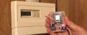
In this post, we will set up an ESP8266-12 to control a relay, which will control the fan on a thermostat. Please do not attempt this unless you are familiar with all safety issues. Use this document at your own risk!
First , we will set up the ESP8266-12F on a breadboard to flash the firmware to the latest version of ESPeasy. ESPEasy. We will use the Arduino IDE to upload a project to the module. This project will only require a few small changes before we upload. We will then use Domoticz server to control an output. This output will turn on a transistor powered relay. The relay will then connect power coming into your thermostat to the fan control of your furnace, however, this setup has limitless other applications, including an input to a ControlLogix system (or other PLC) for non-critical industrial applications.
Breadboard Setup
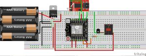
First, let’s make some connections. I’m using the ESP8266-12F, which is soldered to a supernode board. Your pinout may be slightly different if you have a different setup. Just make the appropriate modifications for the hardware that you are using.
On the breadboard, your connections are very critical. In my experience, the most common problem preventing normal operation is bad connections on the breadboard, or a power supply that is under rated.
I’m actually using a 5v, 2A power supply that is going through an LM1117 regulator. (shown by 78xx in the Fritzing image) The regulated voltage of 3.3v will be applied to the power rails.
On the ESP8266-12, connect GPIO 0 and GPIO 15 to GND, and GPIO 2 to 3.3v. These connections will set the boot mode to accept a flash.
Also connect RESET, CH_PD (enable), and vcc to 3.3v, then be sure to connect the GND of the ESP8266 to GND on the power rail.
From GPIO 13, I connected a 780 ohm resistor to the base of a 2n222 NPN transistor. The collector of the transistor will be connected to one side of the relay coil, and the emitter will be connected to GND. To get a higher voltage to the relay coil, I connected the other side of the coil to the unregulated 5v coming into the breadboard.
On your FTDI Programmer, connect GND to the GND rail, TX to RX on the ESP8266, and RX to TX.
As I stated earlier… Most of the problems I’ve had with flash failures and reboot issues have originated from a bad connection on the breadboard, or an improper power supply. This has been a battle for me on almost every breadboard setup with the ESP8266 modules, Another issue I had is that when the ESP8266-12 is plugged into the breadboard, there might not be room for your jumper wires. You can overcome this issue by attaching male to female jumpers on the pins of your ESP board, or in my case, I had mini 400pt breadboards… I just removed a power rail on one of them, and connected two of them together, so the ESP8266 would span across two of the breadboards.
Flash your module
At the time of this writing, ESPEasy can be downloaded here, but if the link has moved, ask Google to find it for you!
https://sourceforge.net/projects/espeasy/
This package comes with a flash utility, so you can power up your ESP8266 and flash your module.
Next, open the .ino file in the arduino IDE. You will need to change the device name, SSID, and Password. Verify your project, and you will find the errors in the results window due to missing libraries. Click Sketch | Include Libraries | Manage libraries, and install the missing library. Repeat this process until you have no errors, then upload the project to the ESP8266.
Energize the Relay
Once your upload is complete, you should be able to power down your ESP, and move GPIO 0 to 3.3v, and power back up watching the serial monitor. You should see that it has connected to your network.
In my case, I used a dynamic address and had to run a network scanner such as angry ip scanner to find the IP Address of your ESP8266. You can also find this on the admin page of your router.
Now, we can issue the command from any web browser to energize the relay:
http://192.168.1.118/control?cmd=GPIO,13,1 (substitute your ESP’s IP address)
To de-energize the relay:
http://192.168.1.118/control?cmd=GPIO,13,0
(If you just enter the IP address into your web browser, you will see the status and configuration screen for the ESP module)
Domoticz
If you wish to have all of your devices in one place, you can install the Domoticz server:
https://domoticz.com/downloads/
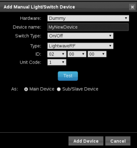
Once the server is up and running, you can create a dummy hardware device, then add your switch as shown… The ID doesn’t matter so much in this case as long as all of your devices have a different ID.
We selected ON/OFF as the Switch type, and LightwaveRF as our device type (just to make the server happy) We won’t test this just yet because we will need to enter our on and off commands in the next step.
Click “Add Device” for now.
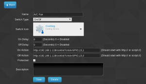 Next, we will edit the switch, and enter our commands as shown:
Be sure to use your own IP address, then press the “SAVE” button.
Now you can click the icon you chose, and your relay should energize. Click the icon again, and your relay will shut off.
Troubleshooting
Things almost never go as planned the first time. If this happens, just relax, get a cold glass of water, and we’ll have to figure out what went wrong.
If the flash failed, check the power coming in to the ESP8266. We should have 3.3v. Also verify that you have a good connection on GPIO pins 0, 2, and 15 (and enable). You might reseat them, or move them to another hole on the power rails.
If the flash was sucessful, but not responding on your network, check the serial monitor when the module boots to make sure the module booted properly. it’s possible that the flash could be corrupted, and you might need to flash again, but most likely if the flash was successful, you probably have a bad connection on one of your breadboard jumpers.
If you sucessfully sent the command to the ESP, but the relay does not energize, be sure 3.3v is coming from GPIO pin 13 after you issued the “energize” command. Also check your voltage across the relay coil. If there is not enough voltage, the relay might not pull in. You may have to adjust the value of the resistor to the base of your transistor, but be careful not to cause too much current flow.
If you have any questions or corrections to this document, please feel free to comment!
— Ricky Bryce