
Introduction to the photoelectric resistor
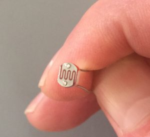 The photoelectric sensor can be used to detect the intensity of a light source. This can be used to detect night and day such as you would see in a night light in your house, or a security light on your garage. In industrial applications, the photoelectric sensor can be used to detect that an object is present on a conveyor, such as a box, or pallet.
In this document, we will look at the resistance of the sensor, and connect this to a simple analog input on our Uno board. Once we are receiving an analog signal, we can use simple compare instructions to use the photo resistor in any project.
Measuring the restance
I used a very inexpensive multimeter that I purchased for $3 at Harbor Freight. On the 20K scale, let’s measure the resistance of simple ambient light on a cloudy day here in Hardin, Montana inside of my camper. 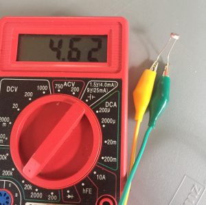
We can see we are getting a reading of 4.62 Kilo Ohms, so we do have a little bit of light in the camper right now. Now, lets put a light source on the photo resistor to see what our measurement is.
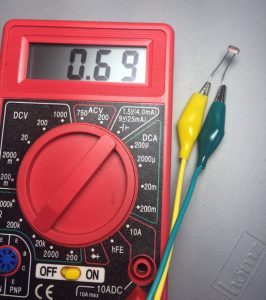
We can see that our resistance dropped significantly to .69 Kilo Ohms or 690 Ohms, so we now know the photo resistor is working well.
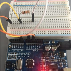 Next, we will incorporate this photo resistor into a project. Since our microprocessor measures voltage, we can use the varying resistance in a voltage divider circuit. We will connect 5v to one side of the photo resistor, then in series with the photo resistor, we will add a 10 Kilo Ohm resistor. The other side of the resistor will be connected to ground. We will take our voltage reading at the point where the photo resistor connects to the 10K resistor. As the resistance of the sensor goes down, the closer our voltage will be to 5v (or 1023 value in our microprocessor). As the resistance increases, we will have more of a voltage drop, and our voltage will decrease. If we want this to work in the opposite direction, we can simple reverse the 5v and GND.
Upload the code
Finally, we will open the arduino analog example sketch. This is under File | Examples | Analog | AnalogInput in the Arduino IDE. We will add the line: Serial.begin(9600); into the setup routine, and Serial.println(sensorPin); into the loop() function as shown:
Note: If you are new to Microprocessors, you can learn more about the Uno board on the post “Getting Started with Microprocessors”.
[code]
/*
Analog Input
Demonstrates analog input by reading an analog sensor on analog pin 0 and
turning on and off a light emitting diode(LED) connected to digital pin 13.
The amount of time the LED will be on and off depends on
the value obtained by analogRead().
The circuit:
* Potentiometer attached to analog input 0
* center pin of the potentiometer to the analog pin
* one side pin (either one) to ground
* the other side pin to +5V
* LED anode (long leg) attached to digital output 13
* LED cathode (short leg) attached to ground
* Note: because most Arduinos have a built-in LED attached
to pin 13 on the board, the LED is optional.
Created by David Cuartielles
modified 30 Aug 2011
By Tom Igoe
This example code is in the public domain.
http://www.arduino.cc/en/Tutorial/AnalogInput
*/
int sensorPin = A0; // select the input pin for the potentiometer
int ledPin = 13; // select the pin for the LED
int sensorValue = 0; // variable to store the value coming from the sensor
void setup() {
// declare the ledPin as an OUTPUT:
pinMode(ledPin, OUTPUT);
Serial.begin(9600);
}
void loop() {
Serial.println(sensorValue);
// read the value from the sensor:
sensorValue = analogRead(sensorPin);
// turn the ledPin on
digitalWrite(ledPin, HIGH);
// stop the program for <sensorValue> milliseconds:
delay(sensorValue);
// turn the ledPin off:
digitalWrite(ledPin, LOW);
// stop the program for for <sensorValue> milliseconds:
delay(sensorValue);
}
[/code]
Verify that your board and port settings are correct, then upload the code.
Testing the code
We will just use our Serial Monitor to monitor the raw analog value coming into our microprocessor. Click on Tools | Serial monitor. You will notice when the sensor reads almost no light (covered up), you will read a value of under 300. In a lighted environment, you will read around 900. Using this sensorValue variable, you can set the threshold at which you would like to take action in your project such as energizing a light. If you are using the Uno Board, you will also notice the LED light will flash faster in a darker environment because the delay is based on the sensor value.
If you have not purchased a photo resistor yet, you can find plenty of them on ebay!
— Ricky Bryce