
Introduction to getting started with EZPLC
Recently, I purchased the starter pack from EZAutomation.net. This starter package came with the processor, power supply, software, and programming cable. I’m used to the RSLogix environment with Rockwell Software. This was a different (but fun) experience for me. At the time, this package was available for around $100, so it was a good time to learn a different platform.
The programming software was a little bit different than what I was used to. I’m writing this post so others can see how to get started with the development environment.
First, you will need to have a serial communication port (COM) port available on your PC. If your PC does not have a built in COM port, you can purchase a USB to serial adapter.
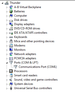
Before getting started, you will need to know the COM port number. You can get this from Device Manager under Control Panel. Then just expand the PORTS. In my case, this was COM1.
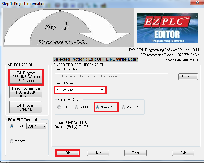
Next, we will open the EZPLC Editor. In this example, we will edit the program offline.
It was a little tricky to select the processor at first. I chose to edit the file offline, as shown. Then I entered the project name. Next, I pressed the OK button. Be sure your COM port is set correctly. Mine was COM1, so I left this setting at default. Finally I was given the chance to select the Nano, and then press OK again.
Adding Logic
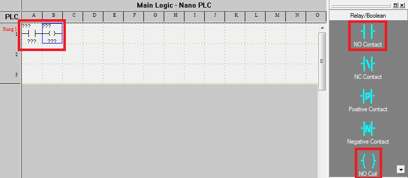
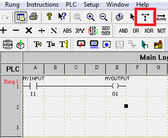
Now we can place our instructions on the first rung. In this example, we will just make an input turn on an output.
To do this, click on the NO (Normally Open) instruction one time, and place the instruction at the beginning of the rung. It will touch the left side of your logic window. Then click the NO Coil, and place it in your ladder window as shown.
Now, we need to address the instructions. We can create our own tag names, but the absolute address of the first input is I1, and the Absolute address of the first output is O1. To get started, just double click on the NO Contact instruction. Realize this does not necessarily represent an actual relay contact in the real world. This instruction simply becomes true when power is applied to the first input.
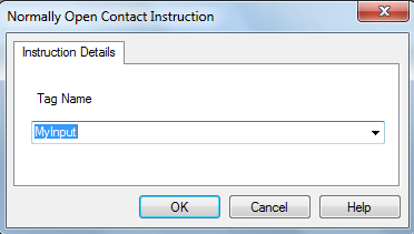
After we double click the NO Contact instruction, we will be asked for a tag name.
Here, I called the tag, “MyInput”, and then press OK.
Now we enter the absolute address, which is I1, then press OK again.
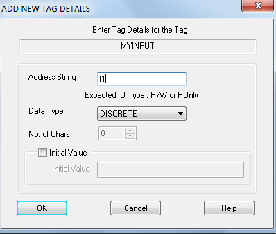
We will do the same thing with the output. Double click the NO Coil instruction. I called this “MyOutput”, and the Address string is O1.
If you wish to space the instructions further apart, just drag the output to the right, and use the “Line” tool to connect the instructions together.
Transfer to PLC
Now we are ready to transfer our logic to the PLC. To do this click on File | Transfer to PLC.
That’s It! Your simple rung is ready to go. Under PLC on the menu bar, you can choose to start and stop the PLC.
— Ricky Bryce