
Introduction to PLC-5 Output modules
The PLC-5 Output modules control devices. In this post, we will discuss the discrete modules (on/off conditions). The Output modules simply act as a switch to turn on or off a load. Examples of field devices attached to output modules include valves, solenoids, indicator lights, and motor starter coils. There are several types of output modules depending on which switching type is required. Triac, Transistor, and Relay control are an examples of the types of switches you might see in your application.
Wiring the Module
Make your connections through a wiring arm that attaches to the chassis. This might also be called a “swing arm”. In the meantime, with a slight twisting motion, apply the wiring arm to the bottom rail of the chassis.
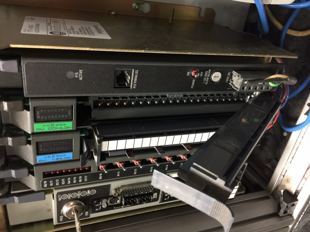
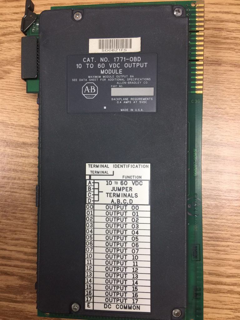
In this case, wire your DC + to the top 4 terminals. This will increase the amount of current that can flow into the card. In the same way, connect your DC Common to the bottom terminal. Connect the other terminals to your field devices. Most importantly, remember that in the PLC-5, all I/O is in OCTAL.
Status Indicators
The status indicators are used for troubleshooting. If a status indicator is on, the processor is calling for the output to energize. To emphasize, this does not mean the field device actually energized. In essence, if the processor calls for the output, and the output is not energized, go to your schematic. At this point, you will trace down the problem in the wiring or field devices.
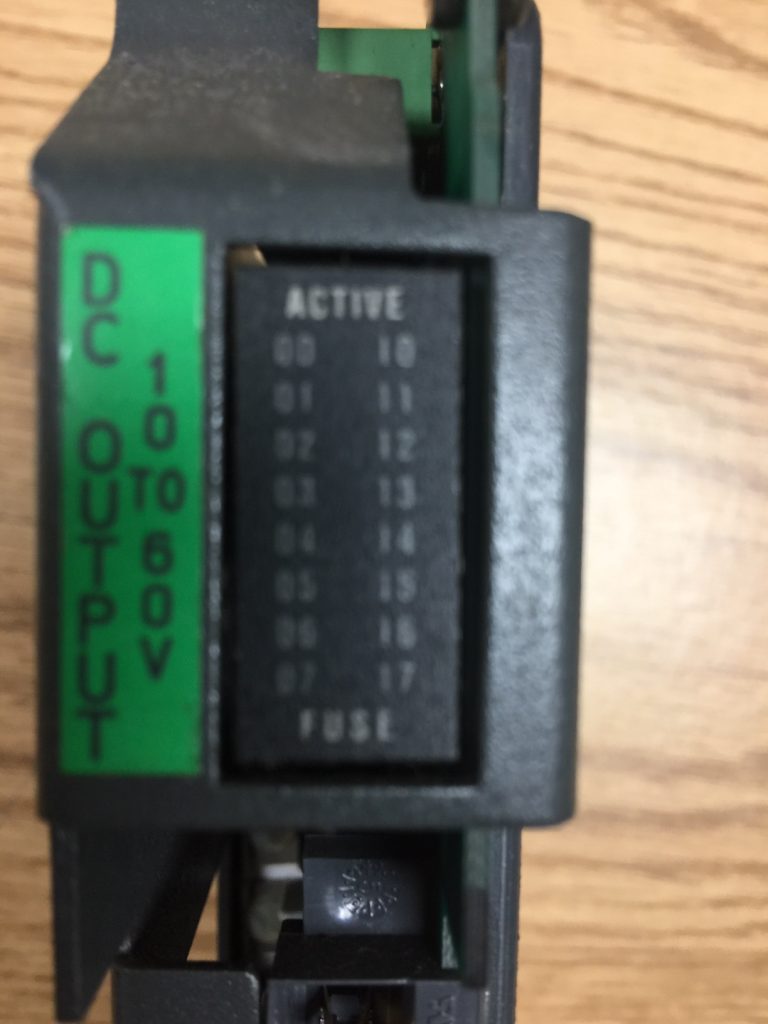
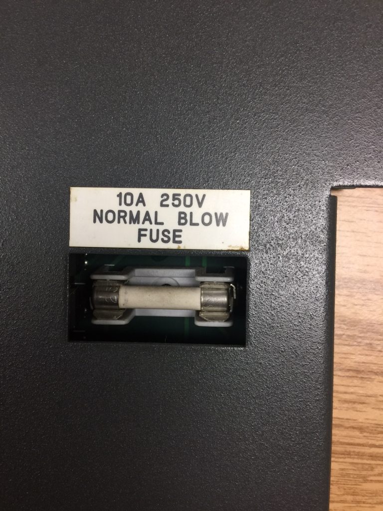
Notice that the output module has a fuse light. If this light is on, the fuse is likely blown. Under those circumstances, replace the fuse on the side of the module.
Other Considerations
Be sure to check the jumper for “Last State” or “Reset”. This jumper sets the condition of the outputs if the module detects a hardware failure.
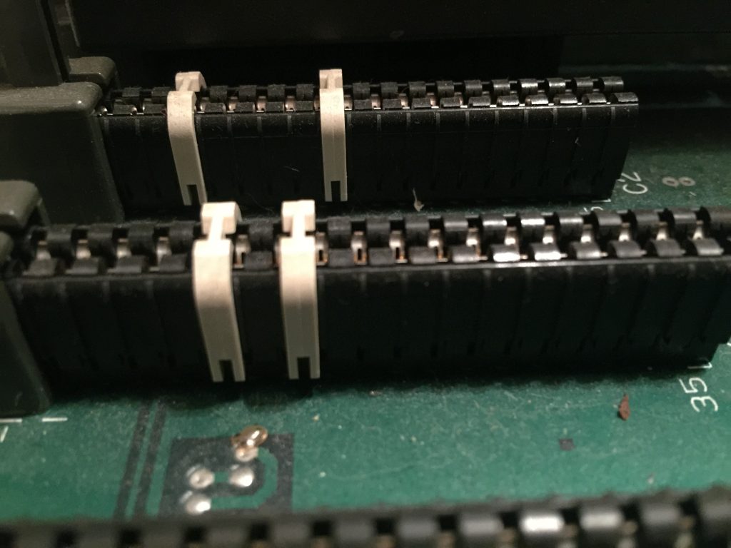
You might also want to check the hardware keys on the chassis backplane. The hardware keys ensure that you can only insert the same type of module into the chassis. Given that, they become brittle over time, and may have fallen to the bottom of your cabinet. For more information on the hardware keys, consult the installation manual.
For more information on the PLC-5, visit the PLC-5 Category Page!
— Ricky Bryce