
Introduction to the PLC-5 Chassis
The PLC-5 Chassis is the device which holds modules. In the PLC-5 system, we will first configure several switches for the desired operation. In this post, we’ll walk through each switch setting for both a PLC-5 Processor, and a 1771-ASB. Another key point is that the chassis comes in 4 sizes: 4-slot, 8-slot, 12-slot, and 16-slot. Shown Below is a 4-Slot chassis. Notice the slot for the processor does not count as an I/O Slot.
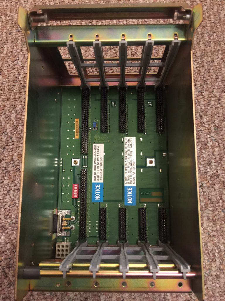
The first thing to remember is that the chassis is not called a “rack” in the PLC-5. The chassis holds modules, whereas a rack is a memory location in the processor.
DIP switches
On the backplane, you see 8 Dip Switches. These switches configure the chassis for the desired operation.
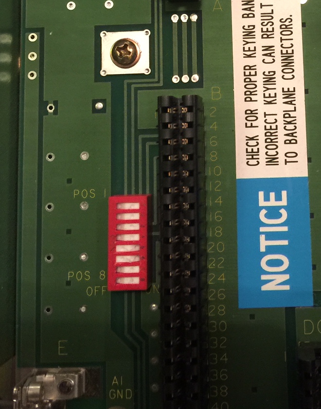
In this case, we have 8 “Rocker” Switches. If we press a switch in on the left, the switch is off. In like manner, if we press a switch in on the right, it’s on. It’s important to remember to not use a pencil point when setting these switches. The graphite could cause the switch to be permanently on.
For a PROCESSOR in this chassis:
Switch 1: Last State — If this switch is ON, the outputs of the chassis will stay in their last state if a hardware failure occurs. Otherwise, they are shut off.
Switch 2 and 3: Always Off — If a processor resides in this chassis, we do not use these two switches. However, these switches could be used if an adapter or PLC-2 processor was in this slot.
Switch 4 and 5: Addressing Mode — The addressing mode tells the processor how many slots equal a group of memory. (A group 16 bits of input and 16 bits of output). If both switches are OFF, every 2 slots equal a group (2-slot addressing). With 4 off and 5 on, every slot equals a group (1-slot addressing). When 4 is on and 5 is off, every 1/2 slot equals a group. (1/2 slot addressing) — Both switches ON is an invalid setting.
Switch 6 and 7: EEPROM Transfer — If you use an EEPROM as an onboard backup of your project, we will need to decide the conditions in which we need the EEPROM to load. With 6 and 7 off, the EEPROM will load at power-up. With both switch 6 and 7 on, the EEPROM will load only if the processor memory is invalid. If there is no EEPROM, or we wish to load the EEPROM manually, turn 6 on and 7 off.
Switch 8: Memory Protect — Turn this switch ON to enable memory protection. This will prevent a user from downloading to the processor, or performing an online edit. Normally, we’ll leave this switch OFF, and memory protection is disabled. This allows us to make changes to the project as we need.
For an ADAPTER in the chassis:
Realize that these settings are different than for a processor. You must take important care to use the correct chart for the settings of your chassis.
Switch 1: Last State — This is for the last state of the outputs if a communication fault occurs. In this situation, leave switch 1 off. The outputs will be turned off if a communication loss is detected. This is usually the recommended setting. If you turn on Switch 1, the outputs will remain in the last state if a communication loss occurs.
Switch 2: Processor Restart Lockout — If this switch is off, the processor will not restart the chassis if a communication loss occurs. You must physically reset the chassis with a reset button on the adapter, or cycle power. When this switch is on, the processor can restart the chassis when communication is restored.
Switch 3 and 4: Always Off — These switches are not used for an Adapter in the chassis. These switches are used for other purposes.
Switch 5 and 6: Addressing Mode — For 2 slot addressing, shut off both switches. Turn switch 5 on, and 6 off, to select 1 slot addressing. Set 5 off, and 6 on for 1/2 slot addressing. Both switches on is an invalid setting.
Switch 7 and 8: Always off — Again, we do not use these if an adapter is in the chassis.
Power Supply Jumper
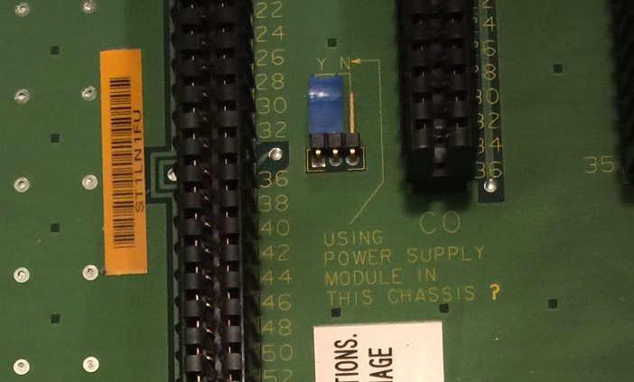
It’s important to remember the power supply jumper. When you use a slot mounted power supply, such as the 1771-P4S, the jumper is in the Y position. However, if you use an external power supply, such as the 1771-P7, set the jumper to the “NO” position.
To verify the accuracy of this information before implementing it in any way, consult the PLC-5 Quick Reference Guide. this is an invaluable tool to have when setting up a chassis!
For other information on the PLC-5, visit the PLC-5 Category Page!
— Ricky Bryce
Appreciate this information. I couldn’t quickly find it on the knowledgebase or in the manual