
Introduction to the PLC-5 1771-ASB (Remote I/O Adapter)
The PLC-5 1771-ASB Remote I/O Adapter allows you to communicate from most PLC-5 processors to a remote Chassis. Not all I/O modules can reasonably reside in the same chassis in many cases. For example: You have 250 points of I/O that are a thousand feet from the processor. One option is to pull 250 wires 1000 feet, back to the main chassis, but remote I/O is a better option. With remote I/O, you mount a chassis at different locations. Using Belden 9463 cable, your local processor will read and write to the remote chassis. Use the 1771-ASB module (instead of a processor) at each remote chassis.
With the most common communication speed (baud rate) of 57.6 K, the maximum remote I/O network distance is 10,000 feet. When using this speed, Both ends of the network are terminated with a 150 Ohm, 1/2 watt, non-inductive resistor. The minimizes the chances of reflections on the network. Higher baud rates (such as 230,4k) will reduce this maximum allowed distance proportionately, and the value of the terminating resistor for this speed is 82 Ohms (on both ends of the network)
Wiring the module
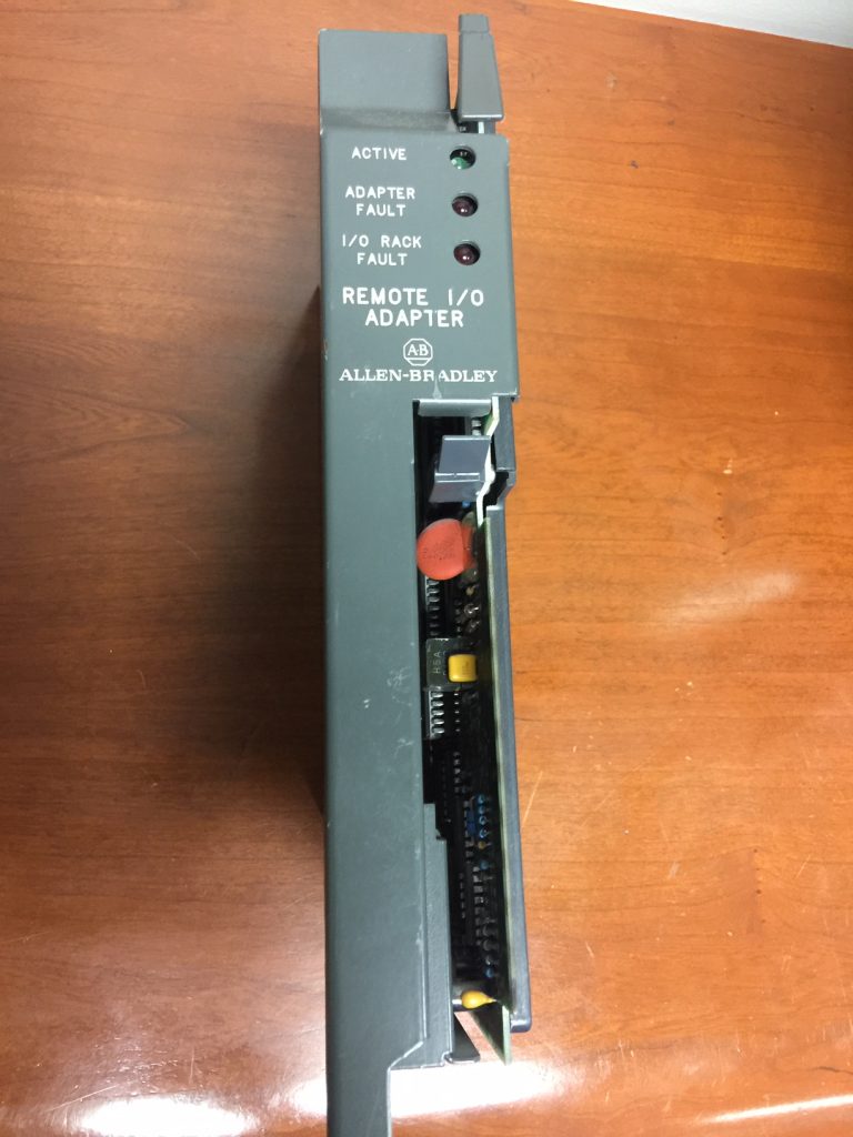
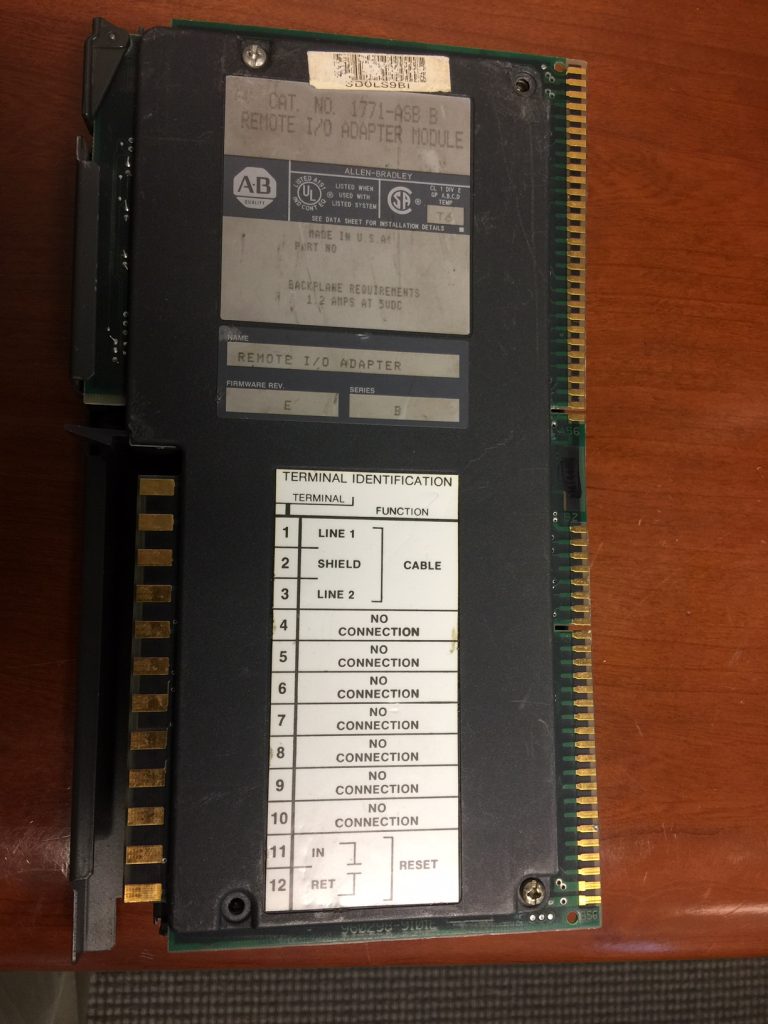
This module requires a 1771-WB swing arm. The side of the module shows a wiring diagram. Connect the Belden 9463 cable to the top 3 terminals (blue, shield, and clear). You can also wire a reset button to the bottom two terminals. The purpose of the reset button is to restart the chassis in the event of a communication failure. When you turn switch 2 of the backplane ON, however, the processor can automatically restart the chassis.
Switch Settings (Series C and D)
In summary, the most important switch settings are the Rack number, Starting Module Group, and Baud rate on the adapter. Switches 5 and 6 on the backplane are also important for determining the addressing mode. Let’s take a close look at the switches on the PLC-5 1771-AS Remote I/O Adapter itself.
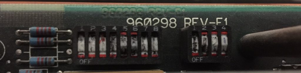
As can be seen, a pen was used to set these rocker switches. Do not use a pencil to set the switches. The graphite could cause the switch to become permanently on.
Press a rocker switch in at the top to turn it on. Press in at the bottom to shut it off.
Addressing
Rack Number
The first six switches on switch bank 1 are for the rack number (memory location) the chassis will begin at. Here, we have Rack #3 (switches 5 and 6 are down). Although you can easily determine the rack number at a glance if you are good in binary, it’s best to refer to the PLC-5 quick reference guide for all of the rack number settings.
Here are the first 7 Rack # Settings (On Switch Bank 1 (SW1))
| Switch 1 | Switch 2 | Switch 3 | Switch 4 | Switch 5 | Switch 6 | Starting Rack # |
| ON | ON | ON | ON | ON | OFF | 1 |
| ON | ON | ON | ON | OFF | ON | 2 |
| ON | ON | ON | ON | OFF | OFF | 3 |
| ON | ON | ON | OFF | ON | ON | 4 |
| ON | ON | ON | OFF | ON | OFF | 5 |
| ON | ON | ON | OFF | OFF | ON | 6 |
| ON | ON | ON | OFF | OFF | OFF | 7 |
Starting Module Group
Switches 7 and 8 will indicate the starting module group within a rack of memory. Remember that Racks and Groups are just memory locations in the processor. Each rack of memory has 8 groups. The most common starting group is 0 (7 and 8 are ON). With 7 ON and 8 OFF, you are selecting group 2. 7 OFF and 8 ON is group 4. Lastly, shut off both switches to select a starting module group (SMG) of 6.
Starting Module Group (SMG) Settings for Switches 7 and 8 on Switch Bank 1 (SW1)
| Switch 7 | Switch 8 | Starting Group # |
| ON | ON | 0 |
| ON | OFF | 2 |
| OFF | ON | 4 |
| OFF | OFF | 6 |
Baud Rate (Communication Speed)
On Switch Bank 2, switches 1 and 2 select the baud rate. Switch 1 ON and switch 2 OFF is 57.6k. This is the most common setting. 57.6k gives you maximum reliability, and a maximum distance of 10,000 feet. To select a communication speed of 115.2k, shut both of these switches off. Although the speed is twice as fast, the maximum distance is halved. The maximum network distance is 5000′. 230.4k is the maximum speed, with switch 1 OFF, and switch 2 ON. However, your maximum distance is 2500′. Be aware that all devices on the same network must run the same baud rate. Be sure to place terminators across the blue and clear conductor at both ends of the cable.
Baud rate settings for switches 1 and 2 on Switch Bank 2 (SW2)
| Switch 1 | Switch 2 | Baud Rate |
| ON | OFF | 57.6K (10000′ Max) 150 Ohm Terminators |
| OFF | OFF | 115K (5000′ Max) 150 Ohm Terminators (typically) |
| OFF | ON | 230.4K (2500′ Max) 82 Ohm Terminators |
| ON | ON | Not used |
Other Settings
Primary / Complimentary Chassis — On switch bank 2, turn on switch #3 to set this adapter up for the primary chassis. In general, I haven’t seen complimentary chassis used much anymore, however, if this was a complimentary chassis, you would shut off switch 3. In summary, complimentary mode allows a chassis to share rack and group numbers with a another chassis with certain restrictions.
Last 4 slots — When switch 4 is off, the processor scans all slots in the chassis. By comparison, turn switch 4 on if the last 4 slots of the chassis are not used. This will free up memory space for other devices on the network.
Series B emulation — For the most part, you will want switch 5 (on switch bank 2) to be OFF. This allows for unrestricted response time. However, this adapter has a series B emulation option if you have older scanners that require a slower link response time.
Status Indicators for the PLC-5 1771-ASB
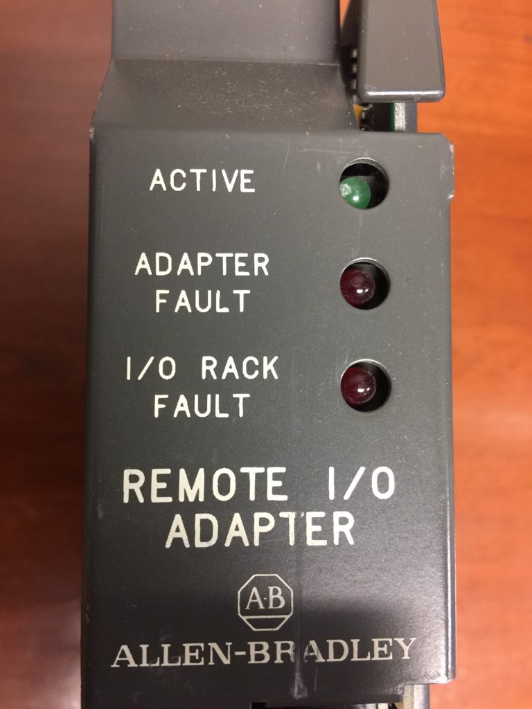
The status indicators are important for troubleshooting the module. There are 3 status indicators: Active, Adapter Fault, and I/O Rack Fault.
Above all, the status indicators are very crucial for troubleshooting your adapter, and remote chassis.
Most Common Status Indicator States for the PLC-5 1771-ASB
Active — We want this light to be solid green. However, if this light is flashing, it’s usually an indication that the processor is in program mode.
Adapter Fault — Normally, this light will be OFF. If this light is solid red, however, that is an indication that we have a bad module.
I/O Rack Fault — If this light is ON, you possibly have a bad module in the chassis, or a shorted backplane. To check this (with your system down), you could try to remove all modules, and replace them one at a time. Also verify all switch settings.
Active and Fault blinking alternately — This is very common if switch 2 is shut off on the backplane. The processor cannot restart the chassis. You can cycle power, or press a reset button if you have one wired to the adapter.
You will find other status light combinations in chapter 5 of the PLC-5 Quick Reference Guide. Refer to chapter 5 for Troubleshooting.
Safety Considerations
This document is simply a guide to help you understand how to configure and troubleshoot the PLC-5 1771-ASB Remote I/O Adapter. Always be fully aware of the results of incorrect module addressing. In any case, if you address an adapter incorrectly, the processor could write to the wrong chassis. This could cause the wrong field devices to energize. Always double check this documentation against the official documentation before implementing it in any way that could cause harm / injury to equipment or personnel. Above all, if you ever remove an adapter for any reason, be sure not to confuse the adapter with the wrong chassis. Switching two remote I/O adapters without setting the addressing properly could have devastating consequences!
For more information on the PLC-5, visit the PLC-5 Category Page!
— Ricky Bryce