
Introduction to PLC-5 Addressing
PLC-5 Addressing is based on a 1970’s I/O Structure. To begin with, all of the I/O is in the OCTAL numbering system. In other words, there are no 8’s or 9’s anywhere in the PLC-5 I/O. To emphasize, timer files, as well as other types of files are in decimal, but All of the real I/O is in OCTAL.
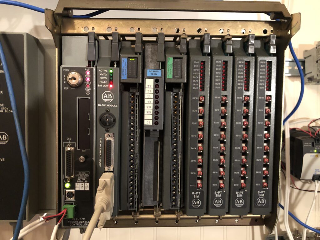
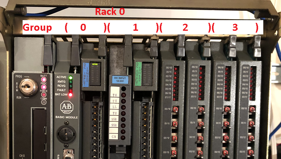
Below is a picture of an 8-slot Chassis that we will use as an example. Important to realize, we need to refer to this as a chassis, and not as a rack. This will avoid confusion with terminology. A Rack is a memory location in the PLC-5 processor.
Terminology
Before we start, let’s get some terminology out of the way. The terminology is very important in understanding how the addressing works in the PLC-5.
Bit — A bit is the smallest unit of information in the PLC-5, and is only 1 or 0. For example, imagine a limit switch. This switch only has 2 states: On or Off.
Word — Words in the PLC-5’s memory consist of 16 bits. The PLC-5 is a 16-bit processor. An example of a word would be an analog module. We cannot express an analog signal as on or off. The bit pattern of a word represents a numeric value for an analog signal. Likewise, a 16 bit input module would also consume 1 word of memory.
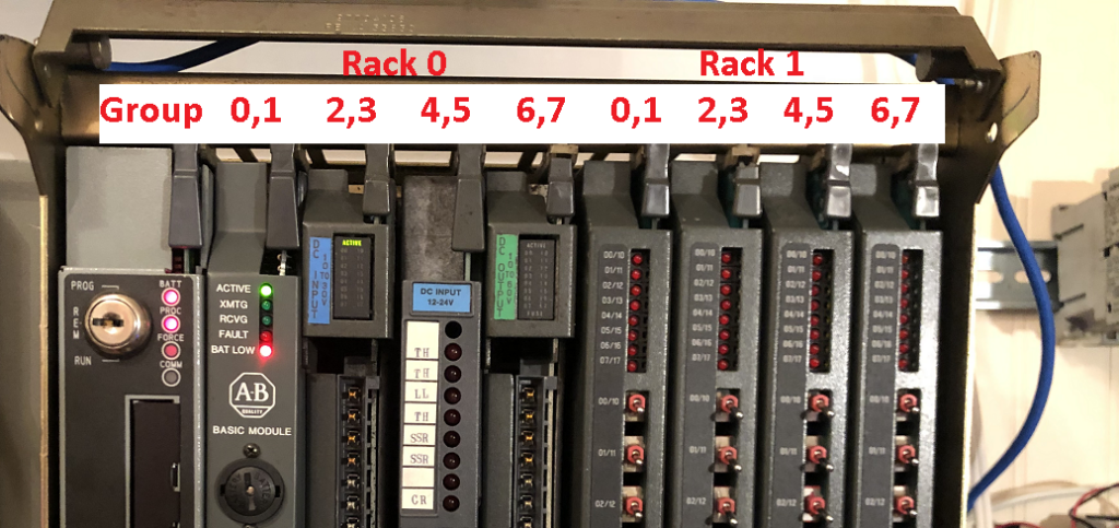
Group — Groups are memory locations consisting of 1 word of input and 1 word of output. Remember, a group is just a memory location, and in no way reflects the actual I/O that we are using.
Rack — A rack is a memory location consisting of 8 groups. Again, remember in no way does this necessarily reflect a physical chassis. Later on, we will map physical chassis into the rack numbers which are memory locations.
Chassis — This is the physical device that we plug modules into. Moreover, a chassis is available in 4 sizes. 4-slot, 8-slot, 12-slot, and 16-slot.
Addressing Mode — Finally, the addressing mode determines how many slots of a chassis equal 1 group. You set this mode by the switches on the backplane. In 1 slot addressing, every slot = 1 group. In 2 slot addressing mode, every 2 slots – 1 group. At last, in 1/2 slot addressing, every 1/2 slot – 1 group. (2 groups per slot).
Addressing Layout
In Short, the PLC-5 Addressing consists of 4 parts. To illustrate, let’s break down these 4 parts.
T:RRG/BB
T — This is the Type, and will be I for Inputs, and O for Outputs.
RR — Secondly specify the Rack number, and always in octal.
G — Thirdly, specify the group number. In order to know the Group number, you must know the addressing mode, and the starting group number of a chassis.
Local Chassis PLC-5 Addressing
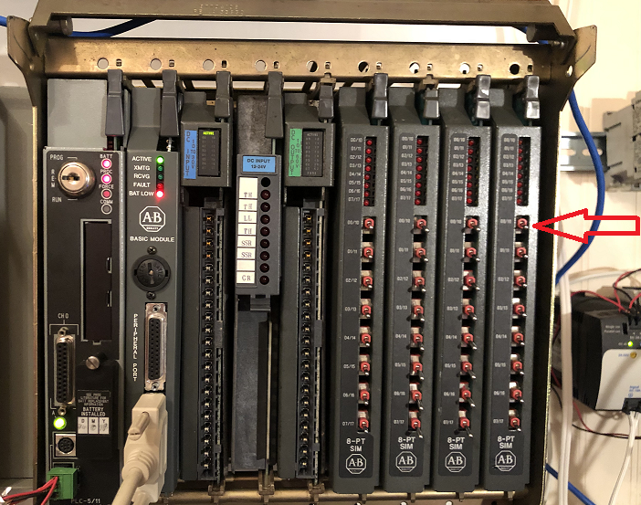
For example, let’s take another look at the local chassis. Let’s address the very first switch of the last module.
We need to know several things before addressing the bit: Rack, Starting Group, and Addressing mode.
Because this is the local chassis, the rack, and Starting Module group are always 0. We don’t count the processor as a group. In this case all we need to know is the addressing mode. We get this from the DIP switches on the backplane. In particular, we will look at switches 4&5.
Behind the processor, you will find the dip switches. Since there is a PROCESSOR in this chassis, use the following chart for switchest 4&5 to find the addressing mode.
Addressing Mode
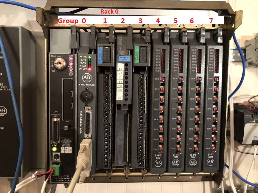
2-Slot Addressing — (Switches 4&5 are both off). Every 2 slots = 1 group. If the above chassis was in 2-slot addressing, the 8 slots would consume 4 groups, which is 1/2 of a rack of memory. Remember, there are 8 groups in each rack. Since every 2 slots = 1 group, and the starting group is 0. Obviously, if this chassis was set for 2 slot addressing, the last module would be in group #3.
1-Slot Addressing — (Switch 4 off, 5 is on) If this chassis was in 1 slot addressing, it would consume 8 groups, which is 1 full rack. Remember, there are 8 groups in a rack, and every slot gets a group. In this case, the last module would be in group 7.
1/2-Slot Addressing — (Switch 4 on, 5 off) If the chassis was in 1/2 slot addressing mode, each slot would consume 2 groups. This is ideal for 32 bit modules, because every slot gets 2 groups. If this chassis was in 1/2 slot addressing, it would consume 16 groups, which is 2 Racks of memory.
Look at the switches below:
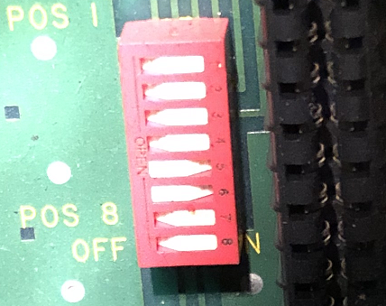
If a switch is pushed in on the left, it’s OFF. Likewise, when you press a switch on the right, it’s ON. In this case, the addressing mode is 1-slot addressing. Therefore, every slot = 1 group.
The address for switch #0 is I:007/0.
2- Slot Addressing — Had the addressing mode been 2-slot, the address would have been I:003/0. Every 2 slots = 1 group.
1/2 Slot Addressing — Likewise, if the addressing mode was 1/2 slot, the address would be I:016/0
Remote Chassis PLC-5 Addressing
On the other hand, let’s look at a Remote Chassis. The same rules still apply. For a remote chassis, we still need to know the Rack, Starting Group, and Addressing mode.
Rack Number
To begin, let’s get the rack number. The rack will be on DIP switches of the remote I/O Adapter. In this case, the adapter is a 1771-ASB. Let’s see what a chassis looks like with a remote I/O adapter in it. Again, we will determine the address of the first switch on the last module.
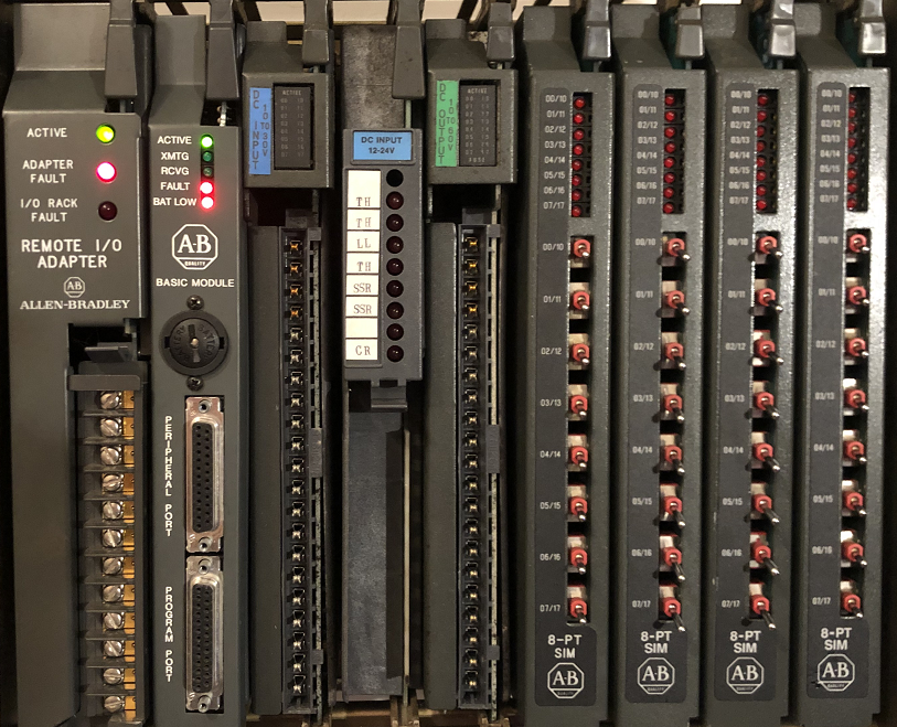
Let’s look at the DIP switches on this adapter.
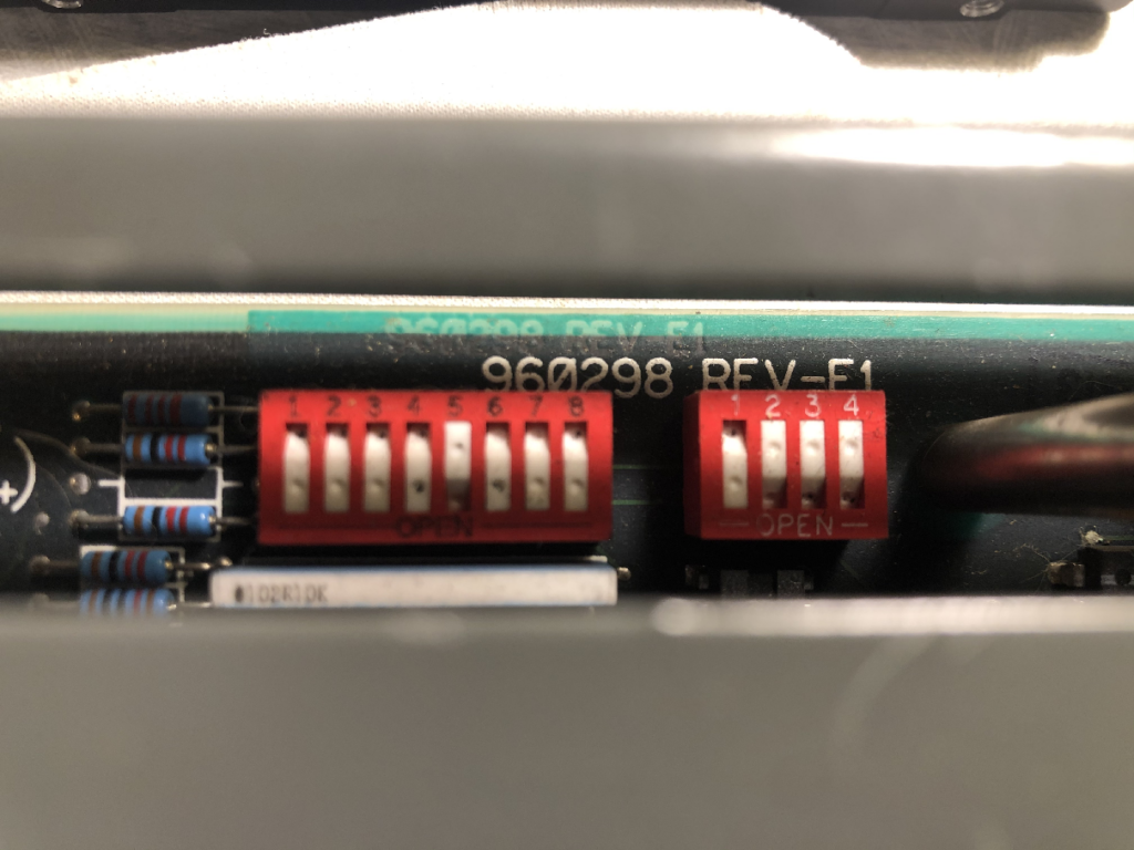
If a switch is pushed in at the bottom, it’s OFF. If a switch is pressed in at the top, it’s ON. To determine the rack number, look at switches 1 to 6 of switch bank 1. Using Down (OFF), as a binary 1, you can derive the rack address. Here, 000010 = 2. This is the rack number. If you are not good at converting between binary and decimal, use a chart in the PLC-5 Reference guide, section 4.
Starting Module Group
We also need the Starting Module Group # within rack 2. To get this, look at switches 7 and 8 on switch bank 1. If 7 and 8 are both on, you have a starting group # of 0. Likewise, 7 on, 8 off is a starting group of 4. 7 off, 8 on, your starting group is 4. Finally if 7 and 8 are both off, your starting group is 6. Obviously, in this case, switches 7 and 8 are both on, so the starting module group is 0.
Addressing Mode
The backplane switches for the addressing mode on a remote chassis are slightly different than the backplane switch settings for the local chassis. This time, we look at switches 5 & 6 on the BACKPLANE. Both off is 2 slot. 5 on, 6 off is 1-slot. Furthermore, 5 off, 6 on is 1/2 slot.
Now that we know the rack, starting group and addressing mode, we can address the first switch of the last module.
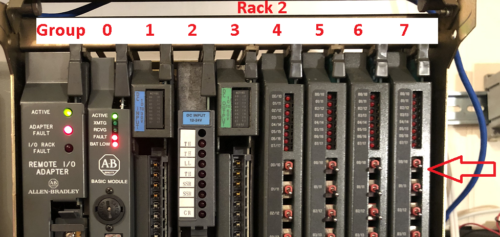
Here, our address would be I:027/0.
Addressing Procedure
- Determine the starting rack number. If there is a PLC-5 processor in the chassis, the starting Rack will be 0. If there is an adapter in the chassis, use the dip switches on the adapter to determine the rack number.
- Likewise, determine the starting module group. If you are addressing a local chassis, this will start at 0. For remote chassis, use the DIP switches on the adapter to determine the starting group.
- Find the addressing mode. For a processor in the chassis, use switches 4 & 5 on the backplane. For an adapter, use switches 5 & 6 to determine the addressing mode.
- If the addressing mode is 1-Slot, write the starting module group on the first slot AFTER the processor or adapter. Number each slot consecutively. These are your group numbers. Do not number past group 7. If the group goes past 7, increment the rack number, and reset the group number to 0 starting at that point.
- If the addressing mode is 2-slot, draw a bracket over every 2 slots, not counting the adapter or processor. Write the starting group # on the first bracket, and number each bracket consecutively. Remember, do not go past group 7. If you need more groups after group 7, increment the rack number from that point, and reset the group # to 0.
- If the addressing mode is 1/2 slot, write the starting group # over the first slot after the processor or adapter. Assign each slot to 2 groups. Again, do not go past group 7. Obviously, if you need more groups, increment the rack number, and reset your group to 0.
For more information, visit the PLC-5 Category Page!
— Ricky Bryce