
Introduction to Arduino Analog Input
In this post, we’ll walk through the example for the Arduino Analog Input. You will find this example under File | Examples | Analog. In this case, I’ll be using the Arduino UNO for this simulation. However, the example will work with many of the other processors.
Basically, we are using a potentiometer. Zero to five volts will give us a value of 0 to 1023. We call this a raw value. Generally, to convert the raw value into engineering units, we need to SCALE this value. Let’s take a look at the example. I’ve developed the snapshots using tinkercad, which is a great tool for simulation.
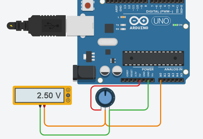
Notice that when the potentiometer is counter-clockwise, the wiper will have 5 volts. It’s against the +5v terminal. Likewise, when the potentiometer is completely clockwise, we will have 0v on the wiper. The wiper is against ground at this point.
Initialize your Variables
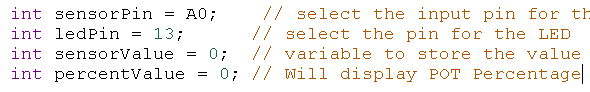
Let’s look at the first few lines of code in the example.
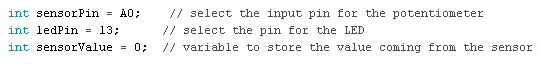
Obviously, all we do here is initialize the variables. The sensorPin is A0. This is what our potentiometer connects to. The ledPin is 13. This is the built in LED for the Arduino UNO. Finally, we need to initialize the sensorValue to hold the data from A0. We initialize this value to 0.
Setup Function for Arduino Analog Input
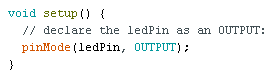
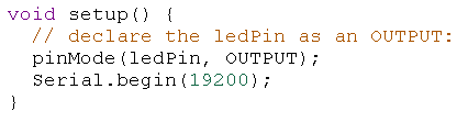
All we need to do in setup is to set the ledPin to output mode. Remember, our ledPin is 13 in this case. This is the LED that is built into the UNO. We do not need to connect an external LED to see this work.
Loop Function for Arduino Analog Input
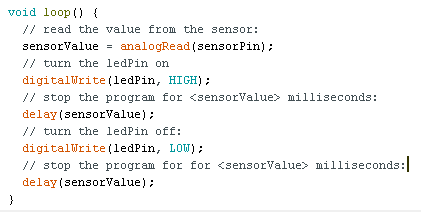
Under the void loop() function, we read the value from the sensorPin, which is A0. Remember this is the pin that our potentiometer connects to. In the next line, we have a digitalWrite. The purpose of the digitalWrite is to turn on the LED. Notice it sets our ledPin to a HIGH state (which is ON).
In the next line, we delay for a certain amount of time. Recall the sensorValue ranges from 0 to 1023. For this reason, when the potentiometer is completely counter-clockwise, we will delay for a little bit more than a second (1023 milliseconds). At this time, we shut off the LED with another digitalWrite.
Lastly, have a delay function for the same amount of time. The process repeats infinitely.
By turning the pot half way, our delay is a little over half a second, so the light blinks twice as fast.
Scale the Data using the MAP Function
First, we’ll initialize another variable in the head of our code. This variable is called percentValue. Obviously, we’ll initialize this to 0. Our goal for this variable is to have it hold a percentage for the pot, which is 0 to 100. Fully clockwise is 0. Likewise, fully counter-clockwise will be 100%.
Likewise, under void setup(), I’ll start the serial monitor. This will allow us to print the value over serial to verify our map function is working.
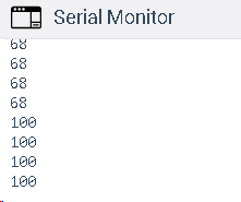
Next, in the void loop(), we scale the value using the map function. We’ll then print the value to the serial monitor. sensorValue is the variable we want to scale. As you can see, our raw value is 0 to 1023, and the scaled value is 0 to 100. Use the example shown below as a guide. Be sure to separate each parameter by the comma.

Lastly, print the value to the serial monitor. When we run the project, you can see our percentValue variable is showing 100% when the potentiometer is fully counter-clockwise.
For other examples for beginners, visit the beginner’s category page!
— Ricky Bryce