
Introduction to the Arduino Analog Output
In this section, we’ll set up an Arduino Analog Output. Analog signals are variable. In contrast, digital (discrete) signals are on or off. On the UNO, pins 3, 5, 6, 9, 10, and 11 support Analog Output. I’ve set this example up on TinkerCad.
For example, we’ll be using the Arduino UNO. The Arduino analog outputs use Pulse Width Modulation (PWM). This is not a true analog signal. All in all though, it does simulate an analog signal. Basically, if we call for 50% output, the signal is high 50% of the time, and low 50% of the time. Likewise, if we call for 75% output, the pin is high 75% of the time, and low for 25% of the time. The cycle happens 490 times per second for most PWM pins. On the other hand, pins 5 and 6 will run at 980 Hz. Check out this link to see what pins support PWM for your particular board.
You can use a PWM to voltage board if you need true analog output. Likewise, you can build your own board with just a few simple components.
It’s important to realize the raw value for 0 to 100% output runs from 0 to 255. The value of 255 represents a 100% high signal while using the analogWrite() function. The format for the analogWrite function is as follows: analogWrite(pin, value); In this case, the pin is 11, and the value runs from 0 to 255.
Arduino Analog Output Explanation
Analog Output Circuit
To illustrate, let’s take a look at the following circuit.
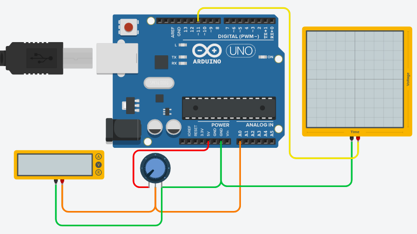
In this case, we have a very simple setup to help understand how the analog output works. The Potentiometer connects to pin A0, giving an input of 0 to 1023 counts of raw data. I’ve scaled the value of 0 to 1023 (analog input) to 0 to 255 (for analog output) before sending it to the analog output pin (11).
We have an oscilloscope on the analog output pin, which is pin 11. To put it another way, as I turn the pot, the output signal goes from 0 to 100% (0 to 255 raw). Fully counter-clockwise is 100%, and fully clockwise is 0 %.
Various Arduino Analog Output Examples
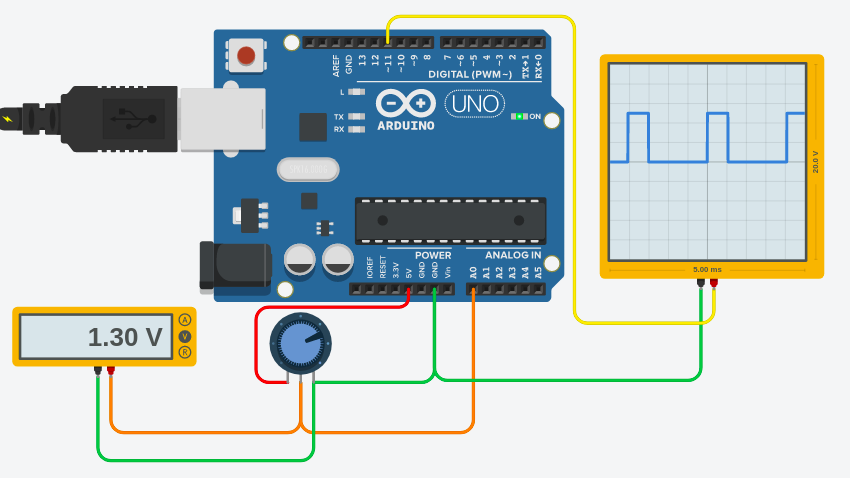
To demonstrate, 1.3volts input is a little over 25%. I’m sending about 25% output to the analog output. You will see what happens on the oscilloscope. You will see a little over 25% “Duty Cycle” for the output.
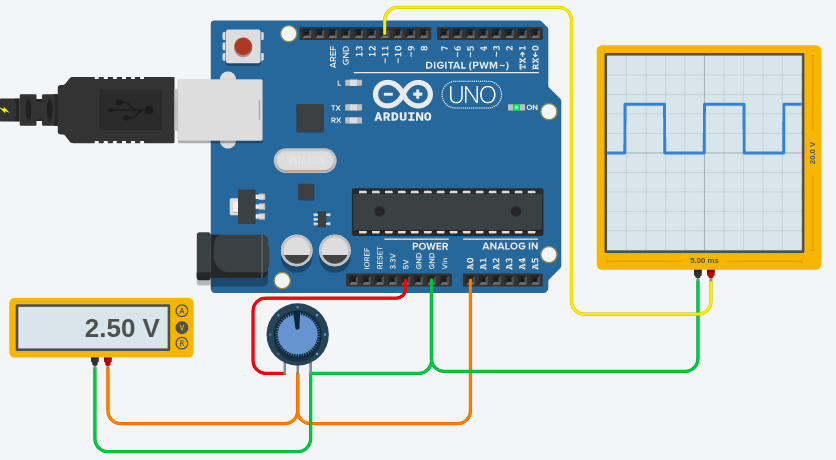
Likewise, we’ll try 2.5 volts. This sends a raw value of about 128 to the analog output. As you can see, the output is high now 50% of the cycle.
On the other hand, let’s try a value of around 75%.

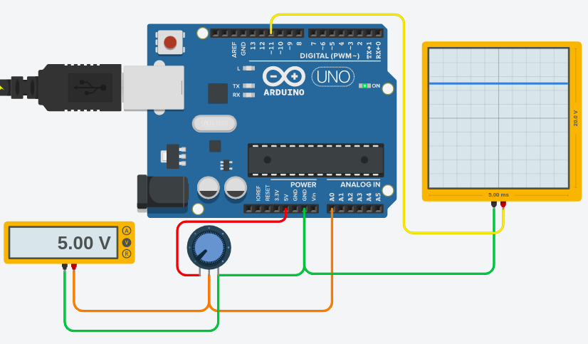
Finally, here is an example of 100%.
Sample Code
I’ve modified the analog input example for this demonstration. The code is as follows:
/*
  Analog Input
 Demonstrates analog input by reading an analog sensor on analog pin 0 and
 turning on and off a light emitting diode(LED)  connected to digital pin 13.
 The amount of time the LED will be on and off depends on
 the value obtained by analogRead().

 The circuit:
 * Potentiometer attached to analog input 0
 * center pin of the potentiometer to the analog pin
 * one side pin (either one) to ground
 * the other side pin to +5V
 * LED anode (long leg) attached to digital output 13
 * LED cathode (short leg) attached to ground

 * Note: because most Arduinos have a built-in LED attached
 to pin 13 on the board, the LED is optional.


 Created by David Cuartielles
 modified 30 Aug 2011
 By Tom Igoe

 This example code is in the public domain.

 http://www.arduino.cc/en/Tutorial/AnalogInput

 */

int sensorPin = A0;    // select the input pin for the potentiometer
int sensorValue = 0;  // variable to store the value coming from the sensor
int rawOutputValue = 0; // Will display POT Percentage
int analogOutputPin = 11; // Analog Output Pin

void setup() {

  pinMode(analogOutputPin,OUTPUT);
  Serial.begin(19200);
}

void loop() {
  delay(10);
  // read the value from the sensor:
  sensorValue = analogRead(sensorPin);

  // scale the analog value, and write to the output pin
  rawOutputValue = map(sensorValue,0,1023,0,255);
  analogWrite(analogOutputPin,rawOutputValue);

  Serial.println(rawOutputValue);

}
For more beginner examples, visit the category page for beginners!
— Ricky Bryce