
Introduction to the Arduino Button Input Example
In this section, we’ll discuss the Arduino Button Input Example that comes with the Arduino IDE. Basically, we’ll connect a button to pin 2, and simply have this button energize a light. Presently, you will find this example under File | Examples | Digital.
The button is a discrete (digital) input. Obviously the only states for a button are HIGH or LOW. Be that as it may, some may also refer to this as TRUE or FALSE, YES or NO, and 1 or 0.
Think of any type of input as STATUS. Obviously, you cannot have the Arduino directly turn on a button. In other words, we simply read whether the button is pressed or not. Other examples of discrete inputs include a relay contact, pressure switch, or float switch. In short, a discrete input is any type of switch.
Schematic for the Arduino Button Input Example
I’ve built this schematic using Tinkercad. This is a very handy tool on the web for testing your circuits before you actually wire them.
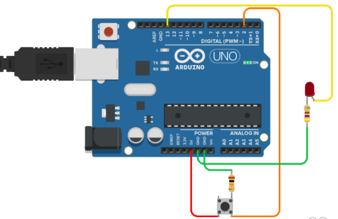
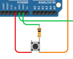
Most of the confusion is on the button itself. It’s important to realize that the two pins on the left side of the button connect together internally. Likewise, the two pins on the right side of the button are electrically the same. If you are unsure of how your button works, check the continuity between pins without pressing the button. After that, press the button to see which pins connect together.
Button Circuit Operation
Before we start, take a look at the button circuit itself. The red wire brings 5v into the button. on the left side. In short, when you press the button, this 5v will pass to the orange wire, which connects to pin 2 of the arduino. This takes Pin 2 to a HIGH state.
You will also notice that electrically Pin 2 connects to ground through a 10K resistor. The purpose of this pull-down resistor is to bring PIN 2 (orange wire) to a LOW state when you release the button. That way, you don’t have a “Floating” voltage on Pin 2.
When you press the button, you WILL have some current flowing to ground through the 10K resistor. Because there is very little resistance through the button, however, this is not enough to significantly pull the voltage down going to PIN 2 when you press the button.
When you release the button, the orange wire connects to ground through the 10K resistor. Basically, this pulls PIN 2 (orange wire) back to a LOW state.
LED Circuit Operation
The LED is sensitive to Polarity. That is to say, it matters which side you connect to +. In this case, the longest lead of the LED connects to + through a 470 Ohm resistor to limit the current. Likewise, the FLAT side of the LED connects to GND. In short, it does not matter which side of the LED the resistor is on, but it does matter which side connects to + and GND.
Code for the Arduino Button Input Example
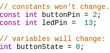
The code for this example is straight-forward. First we initialize some variables. The buttonPin will be #2. Likewise, the ledPin is 13, which is also the built-in LED on the UNO. In the same fashion, we’ll initialize the buttonState variable to 0.
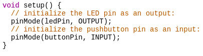
Next, we have the void setup() Function. We simply set pin 13 (ledPin) to OUTPUT mode. Likewise, we set pin 2 (buttonPin) to INPUT mode.
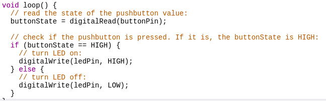
In the void loop() function, we are always reading the state of the button. If the button goes high, set the ledPin to a HIGH state. On the other hand, if the buttonState is LOW, set the ledPin to a LOW state. It’s important to realize the “=” is an operator. It sets a variable to a specific value. The “==” is a comparator. That is to say, it checks to see if a variable is equal to a certain value. A common mistake in code is to use the = where the == should be used. When this happens, you inadvertently assign a variable to a certain value instead of simply checking to see if it equals that value.
For other examples, visit the beginner’s category page!
— Ricky Bryce