
Introduction to the ESP-01 with TM1637
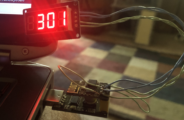
Using the ESP-01 with TM1637 is a very cost efficient way to make a nice display. Obviously, you can use this combination to make a clock, display a value from Mosquitto (MQTT), or any other value. In this post, I’ll be using the TM1637 Library by Avishay Orpaz. Overall, we will only need to make one modification to the code for the demo to work: The DIO pin will be 0.
Hardware for this Demo
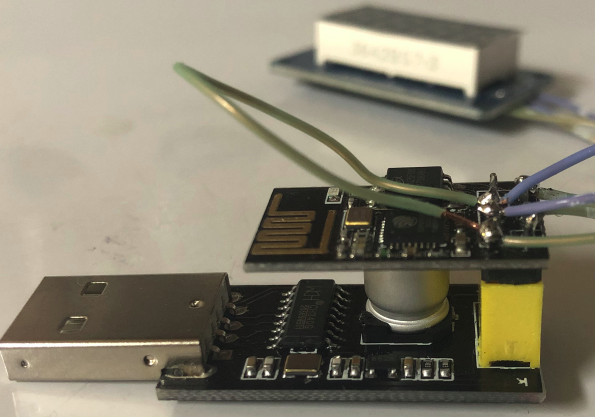
Obviously, we will need a few hardware components. First, we need an ESP-01 processor. This processor has built-in wifi, and is of the ESP8266 series. Secondly, we’ll need a TM1637 Display. Thirdly, I will use a USB Programmer for the ESP-01. Lastly, you will want some wire and soldering tools.
Make the Connections
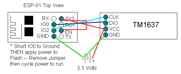
VCC and GND (On the ESP-01) connect to VCC and GND on the TM1637 Display. GPIO2 on the ESP-01 will connect to your Clock Pin (CLK) on the TM1637. Likewise, GPIO0 connects to the DIO Pin on the TM1637.
Additionally, we will need a couple jumpers on the ESP-01. 3v3 connects to EN. Temporarily connect GPIO0 to GND. This is to flash the module. After you upload your program, remove the jumper. In this case, I simply soldered a wire to GPIO0, then touch it to GND when I need to upload.
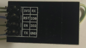
Be careful when you are soldering the wires. Be sure you have the orientation right if you solder on the top side.
Uploading the Code
If you haven’t done so already, go to Tools | Manage Libraries. Be sure to connect your jumper between GND and GPIO0, then plug in your module. (Plug in the module AFTER you make this connection). Search for TM1637. The library I chose was from Avishay Orpaz. for this example. Under tools, go to “Boards”, and choose the Generic 8266 Module. If this is not an option, go to File | Preferences, and enter http://arduino.esp8266.com/stable/package_esp8266com_index.json into your boards manager. Be sure to click Tools | Port to choose the correct port that your ESP-01 is connected to.
Under the definitions section of your code, change the DIO Pin to 0. Upload your code.
Unplug the module, remove your jumper between GPIO0 and GND. Plug your unit back in and you should see the demo run!
For more information on other simple projects, visit the Arduino Beginner’s Page!
— Ricky Bryce