
Introduction to ESP-01 with I2C LCD
In this section we’ll discuss setting up the ESP-01 with I2C LCD. I’ll use the LiquidCrystal_I2C Library. For the Generic ESP8266, this shows up as Incompatible under examples. Nonetheless, we’ll make a few modifications for it to work with the ESP-01. By using this method, I didn’t have any problems using this library. Nonetheless, you should thoroughly test your project when it’s set up to ensure it’s working properly for you. I’ll be using the “Hello World” Example in this post.
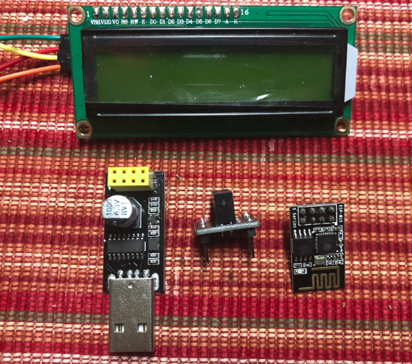
Hardware Used
For example, I’ll be use the ESP-01 processor, A USB programmer for the ESP-01, and a 16×2 LCD Display. You will also need a breadboard, breadboard adapter for the ESP-01, or some soldering tools and wire. I’m setting this up on a breadboard. For this purpose, I’ll also need a 5v power source as well as a 3.3v power source.
Programming the ESP-01
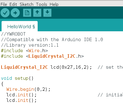
Before you upload your project, double check the I2C address. In this case, it will be 0x27. Also, verify the columns and rows are set correctly on the same line. For example, I’m using a 16×2 display. Another common address is 0x3F. At the same time, I’ll add the line Wire.begin(0,2); at the top of the Setup routine.
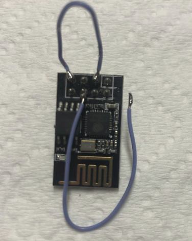
Before uploading, be sure you have EN jumpered to 3v3. Furthermore, I’ve added a temporary jumper to GPIO0. Temporarily hold this jumper to GND, and insert the programmer with ESP0-1 into your USB Slot.
At this point, upload your project, and then remove the jumper between GPIO0 and GND.
Wiring Connections for ESP-01 with I2C LCD
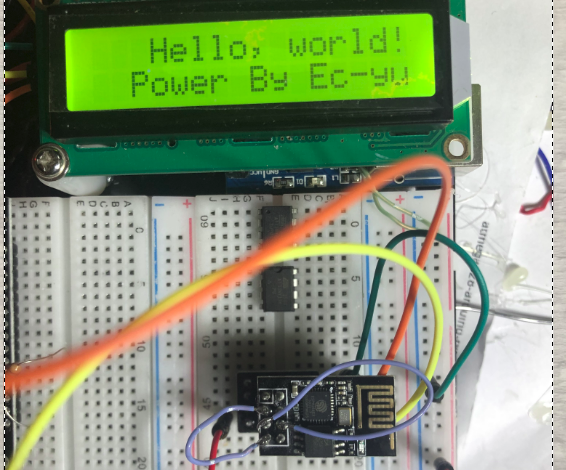
After the ESP01 is programmed, the connections are very straight-forward. Connect VCC on the ESP-01 to 3.3v, and GND to GND on the breadboard. Likewise, connect VCC on the LCD to 5v, and GND to GND on the breadboard. Be sure the GND is common between both the ESP-01, and the LCD. GPIO0 on the ESP-01 connects to SDA on the LCD. At the same time, connect GPIO2 on the ESP-01 to CLK on the LCD. Furthermore, double check your jumper between EN and VCC on the ESP-01. By all means, make sure you have removed the flash jumper between GPIO0 and GND.
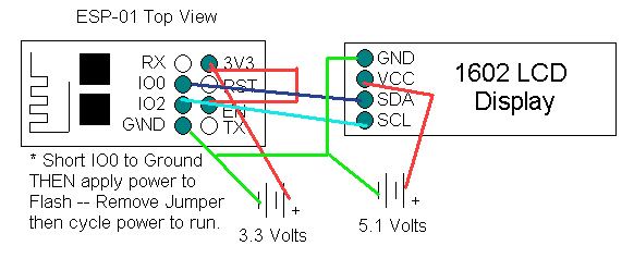
Once you power up, you should see text on your display. You may have to adjust the pot on the back of the I2C LED display to adjust your contrast.
Troubleshooting
If you cannot upload your project, double check the selected board and COM port. I used the Generic ESP8266 Module setting. Check for the correct setting of your Port under “Tools”. Another key point is to make sure you jumper EN to 3V3, and that GPIO0 is to GND. If your display does not work, try changing the address. In this case, I had to change my address to 0X3F, then upload again. If you still have a problem, check all of your voltages and connections.
Arduino IDE gives me this warning:
WARNING: library LiquidCrystal_I2C claims to run on avr architecture(s) and may be incompatible with your current board which runs on esp8266 architecture(s).
I tried it anyways, it did not work.
Hello, Cindy…
I’m just curious. Did you try to change the I2C Address to 0x3F? Some of my LCD’s run on 0x27, and some run on 0x3F. I’m also curious about the distance you are running between the ESP-01 and the LCD Display. Another question would be if you are running the ESP-01, or another version of the board such as the 12E. For the 12E development board, I just commented out //Wire.begin(0, 2); Then, I just ran SCL to GPIO5, and SDA to GPIO4. I’ve been running that setup here on 5 different units, and they are working well. Let me know how it goes! — Ricky
I wasn’t sure if I2c works on ESP-01s, It does! I had issues, due to mistakes and flaky contrast pot on my LCD, but things to check
to confirm LCD I2c address, you can use the I2c_scanner script but modify the code, add 0,2 on wire line to read : Wire.begin(0,2);
a mistake I made is I forgot to change board from nano to ‘Generic ESP8266 module’ and check the LCD contrast pot!.
Thank you R.B for the help.
No Problem, Cindy… Thank you for updating your post. Everyone learns a lot when we have issues like this! I’m glad you have it running now! — Ricky
What LiquidCrystal_I2C library are you using? I am trying to lcd.print(“x”) and lcd is showing little arrow symbol. The backlight command works as expected. I have scoped SDA and SCL – both look perfect. Thank you for the posting – it did help get me started.
I believe I was using the LiquidCrystal Arduino library for the DFRobot I2C LCD displays. Sometimes, there are so many different libraries, it’s hard to choose which one to use. It sounds like you have the address correct if you can get the backlight to energize. What happens when you try different text than an X? Does the symbol change from an arrow to a different character? Check to make sure all of the data pins are soldered properly to the backpack, and that the backpack is not shorting against the LCD Board.