
Introduction to the Infrared Obstacle Avoidance Sensor
The Infrared Obstacle Avoidance Sensor allows us to detect the presence of an object with no contact. For this reason, the module has very little mechanical wear. For example, if you are building a robot, you can detect the presence of an object that you need to avoid. Additionally, if you have a matchbox race car track, you might use this sensor to identify the start and finish time of each car. Another use is to detect if a door or window is open or shut.
In this case, I’m using the ESP-01 microprocessor with the Infrared Obstacle Avoidance Sensor. This will detect if a door is open.
Hardware
For this example, I’m using an ESP-01 microprocessor. I’ll also use a Flying Fish MH-Series sensor. Additionally, I need a breadboard adapter for the ESP-01, and a USB programmer for the ESP-01.
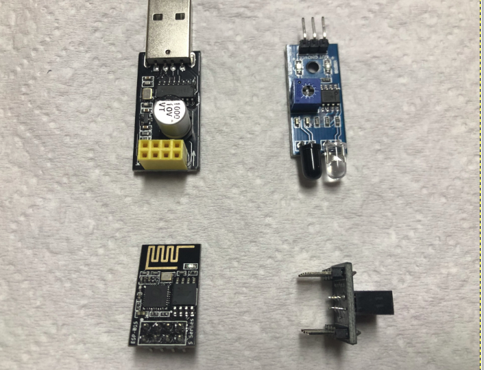
If you are using a standard Arduino, you will likely not need a special programmer or breadboard adapter.
Programming
The programming is very straight forward. We’ll just use GPIO0 as the input pin. At the same time, I’ll send the restul to the Built-In LED which is GPIO2.
const int SensorPin = 0; // I'm wiring the Sensor to Pin #0
const int LightPin = 2; // I'm connecting an LED to Pin #2
int SensorState = 0; // This will be our Sensor variable
void setup() {
pinMode(SensorPin, INPUT); // Set the SENSOR pin to INPUT mode.
pinMode(LightPin,OUTPUT); // Set the LIGHT pin to OUTPUT mode.
}
void loop() {
// Read the sensor state
SensorState = digitalRead(SensorPin);
digitalWrite(LightPin,SensorState);
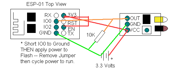
}Because I have an ESP-01, I will need to make a couple connections before uploading. Jumper EN to 3V3. I also need to temporarily jumper GPIO0 to GND on the ESP-01 to flash (upload) to the module.
With GPIO0 connected to ground, I will insert the ESP-01 into the USB programmer. Finally, I will upload the project.
Connections
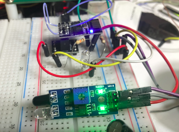
Finally, we’ll check our project. Connect GND on the ESP-01 to GND on the Sensor. Likewise, connect 3V3 on the ESP-01 to VCC on the sensor. Additionally, connect GPIO0 to the output of the sensor. Lastly, for my module, I will place a 10K pull-down resistor between the output pin and GND. Be sure you have a 3.3 volt supply going to 3V3 and GND of the ESP-01. Obviously, this voltage is also sent to the sensor. Furthermore, to spice things up a little bit, I placed an LED onto GPIO0 in series with a 1k resistor. On my module, the built-in LED was active low. This LED is active high. Therefore one light will energize when an object is detected. The other light will energize when no object is detected. It’s important to realize the pin will be LOW when an object is detected.
Test your work
Move your hand in front of the sensor. You will see the LED shuts off. This means it has detected an object. Adjust the potentiometer to change the distance the sensor will read. With my setup, I checked the default distance setting at around 4 inches. The maximum reliable setting was about 7 inches.
For more information on other projects, visit the beginner’s category page!
— Ricky Bryce