
Introduction to the LM7805 and LM1117t (3.3v Version) Voltage Regulators
The LM7805 and LM1117t Voltage Regulators will reduce the DC Voltage in a circuit. There will be some amount of power loss in the linear regulators that will produce heat. If you produce too much heat, the regulator will go into thermal shutdown. On the other hand, you can reduce heat by decreasing the input voltage, or by decreasing the load. Obviously, each regulator must be supplied with an input voltage that is higher than the output voltage. The LM7805 should be supplied with at least 7 volts. In contrast, the LM1117t must be supplied with at least 5 volts.
Power Loss
The input and output current are the same for these linear regulators, however, the input voltage is higher than the output voltage. This causes power loss equivalent to the current times the difference between Vin and Vout. For example… Our load is 200mA on the LM7805 regulator. If we have an input voltage of 7 volts, we’ll have an output voltage of 5 volts. In this case, the voltage difference is 2 volts. Power is equal to current times voltage. Therefore 2 volts times 200mA (.2A) would be a power loss of .4 Watts. If you supply the regulator from a 9 volt battery however, your power loss is .8 Watts. This power loss translates to heat. As I have said, if the regulator generates too much heat that it can’t disparate, it will go into thermal shutdown.
Capacitors
Each regulator should have two capacitors. One capacitor on the input side, and one for the output. You should connect these capacitors between the positive and ground (or common). The input capacitor filters ripple from the power source. In contrast, the output capacitor provides voltage stability for the load. For consistency, I always use 10uF capacitors. However this can be anywhere from 1uF to 10uF unless you have a reason to use something different. For example, you might lower the value if you expect high frequency ripple. I put together the following diagram using TinkerCad.
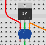
As you can see. I’ve added a capacitor to each side of the regulator, and the center connects to common.
7805 Voltage Regulator
In summary, the 7805 regulator provides 5v of output when you provide a minimum of 7v. The maximum voltage is 35v. It can provide up to 1.5A of current. With attention to the heat buildup, you might want to add a heat sink. On the 7805 regulator, the left pin is input, and the right pin is output. The center pin is your common.
1117t Voltage Regulator
By contrast, the 1117t regulator provides 3.3v of output with a minimum input of 5 volts. The maximum voltage is 15v. Maximum current for this regulator is 800mA. However, be careful that you are dissipating the heat properly. It’s important to realize the pinout is different from the 7805. The left pin is GND, the center pin is output voltage, and right pin is y our input voltage.
It’s important to realize that each regulator has some variations based on it’s inherent design and full part #. Always consult the datasheet for the exact regulator that you are using.
Summary
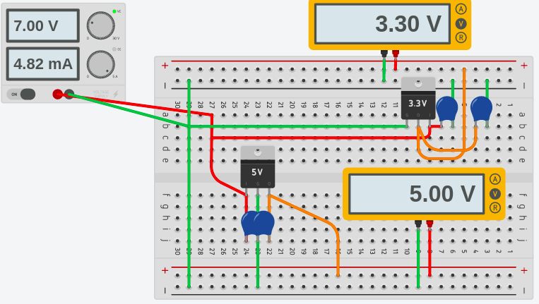
To summarize, I’ve set up a breadboard with a 5v regulator and a 3.3v regulator. As you can see, the top rail is 3.3v, and the bottom rail is 5v.
For more information, visit the arduino beginner’s page!
— Ricky Bryce