
Introduction to the Transistor Controlled Motor
In this post, we’ll set up a Transistor Controlled Motor. The transistor allows us to control a larger current by applying a small amount of current to the base. If we control this motor with an arduino, we wouldn’t want our control current to be over 20mA for very long. Microprocessors have strict current limitations. For this reason, we use the transistor as a switch. In this case, a very small amount of current will flow through a push button (which simulates an output of a microcontroller). In turn, this allows a large amount of current to flow to the motor. Always check the specifications of your motor, and the current limitation of the transistor you use! Be sure the current draw of your motor does not exceed the limitation of your transistor.
The Transistor
Basically, in this circuit, the transistor is a switch. Personally, I like to use the 2n2222 for such applications. For example, we have an NPN transistor. Whenever you apply a positive charge with a certain amount of current flow to the base, the transistor will start to conduct. Current flows through the motor, then through the collector of the transistor. At this point current flows from the emitter of the NPN transistor to the negative side of the power supply. For an NPN transistor we interrupt the negative side of the load. On the other hand, if you wish to interrupt the positive side of the load, use a PNP transistor. Always check the data sheets and wiring diagrams of the transistor you wish to use.
Microprocessor
In this case, we have no microprocessor. For the purpose of simplicity, we are controlling the load with a button. Microprocessors such as the Atmega328 have a maximum current limit of 40mA per pin. It’s not a good idea to run 40mA for long though because of heat buildup. For this reason, I’ll always limit the current flow to 20mA per pin.
The Motor
Overall, the motor will pull around 81mA of current when running full speed at 5v. Every motor will be different, so be sure to check the specs of the motor. Keep in mind that our motor is an inductive load. In other words, it creates magnetism. When we shut off the motor, the magnetic field will collapse and produce a high voltage in the opposite direction of the force that caused it. For this reason, I’m reverse-biasing a diode to place across the motor. The diode will suppress this voltage spike in the opposite direction.
Our Circuit
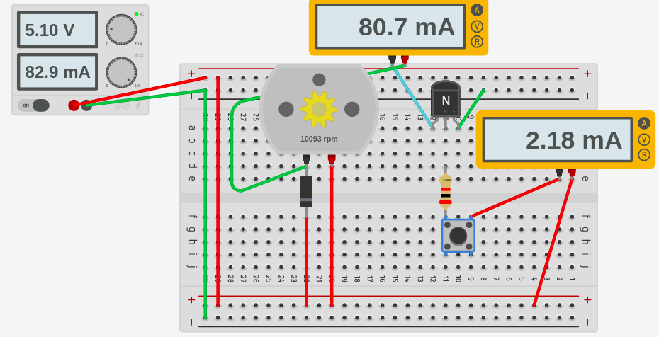
As you can see, below, I’m applying 5.1v to the breadboard. However, the button is open. In other words, no current flows to the base of the transistor. Therefore, the transistor does not conduct, and the motor is not turning. I created these drawings with Tinkercad.

Finally, I’ll press the button. This applies a positive current flow to the base of the transistor. We absolutely must have the 1K resistor to limit the flow of current to the base. As you can see, the current flowing through the button is only 2.18mA. This is well below or 20mA limitation that we like to see on a control device, such as the Atmega328 (Arduino’s processor).
At this point, the transistor conducts. Because 1K is such a low value of resistance, the transistor fully “turns on”. After the transistor turns on, current flows through the motor, then through the transistor to ground. The motor is pulling close to 81mA.
For more information on basic microprocessor labs, visit the beginner’s category page!
— Ricky Bryce